Relativity and technology in the new hydroelectric energy.
Relativity and technology in the new hydroelectric energy.
(The conservation and the transformation of sustainable energy resources)
By Luigi Antonio Pezone
- ABSTRACT
With this article research, I refer especially to the fathers of the science in the era before the industrial era, used the only reasoning to find links between the laws of space, matter and nature. With industrialization were born the specializations and these ties have been lost the global reasoning of science. How modest designer, but above installer of systems, which has had the opportunity to range among the industrial, environmental and energy, I could not notice that there are huge gaps between a plant and another, even within the same systems, both in areas depurative, both in those energetic, both in management of hydraulic resources. The science of the past was universal while the modern that develops in laboratories has become partisan. The technology that did not exist was launched on the same street. He has made enormous progress and modern companies are super specialized in individual areas, but from an environmental perspective, there is no complete system in the world. I do not doubt the good faith of the experts, but I also believe that cannot do full environmental reasoning if not are put together technical and transversal scientific knowledge and do not set the global cycles that are simultaneously purifying, energy and management.
This publication is a summary of some environmental patents, above all, related to water management and hydropower generation, different from the current. They are making a very difficult path to be understood, just because of the fact that none of the experts, public and private is accustomed to think globally, but entering into details, purification, energy and management. Unfortunately, this is the only way to realize the synergies that serve to arrive at a comprehensive environmental management that does not waste resources. Who has believed, for economic reasons, to neglect the global management of the environment, only focusing on energy production, more or less clean, to be sold on the international market, will be surprised and disappointed because the global management will produce energy clean tens of times more economic than the current ones. We just have to wait and see until the authorities, science of part and the economy, will pretend not to understand these inventions, which are available for all, especially for poorest and those looking for work. Because there is work for everyone if we want to correct the mistakes of the past and present.
keywords: submerged hydroelectric, hydroelectric with water recycle, hydroelectric with lifting water, mobile pressurized hydropower, hydroelectric combined with artificial welling, dual supply pumps.
2) INTRODUCTION and METHODS
The famous scientist Albert Einstein and his theory of relativity, demonstrated that matter and energy can be considered as a unit, given that one can become the other according to a precise mathematical relationship. A practical confirmation of this statement we can find in the action of the wind can generate electricity through wind turbines but can also break the inertial balance between the troposphere and hydrosphere, creating kinetic energy in ocean currents. This, for myself, is the energy aspect underrated in the world, because even we can break this balance, artificially, by means of intubation of a small stream of water, a pump placed in the depth of the water and concentrate all ‘kinetic energy produced on the blades of a hydraulic turbine. There is no law of conservation of energy that can prevent it and no energy balance to do, except that between the energy used and that produced, because we take energy from an endless source. The difference between expenditure and energy produced is immense, in favor of the energy produced, because we are not in an isolated system as the pendulum of Newton. In fact, all the weight of the water column intubated (m * g * h) gains kinetic energy (1/2 mv2) braked by the blades of the turbine, which produces electricity by alternator connected, under the weight of the water masses conveyed on the turbine to the effect of gravity and atmospheric pressure, once moved the masses of water below by means of the pump. In fact, Einstein says that the energy provided it does not increase the speed of the body, but its mass: the body becomes more and more “heavy”. This is also reflected in the practical calculations of the prevalence of lift pumps which is subtracted from the positive head on the suction side, being considered an energy in all respects. This energy becomes even more important if instead of raising the water we use pumps to produce energy. In this case, it is convenient that pumps orient the flow of the flow in the direction of the force of gravity and atmospheric pressure. Using this system the difference between the energy used and that produced becomes huge because the surface water has the same density as water below, and therefore does not need to rise to the surface, if we are in a small basin (The water simply changes position). The energy production is huge, as realized in terrestrial hydroelectric, at atmospheric pressure, because the exit of the turbine the hydrostatic water pressure cannot oppose the kinetic energy remaining. In fact, because water is incompressible, at any depth is on the outlet, the hydraulic resistance to the output is always the same (v2 / 2g). Therefore, energy expenditure may be multiplied by a hundred, two hundred, etc. It depends only on the water column, which weighs on the pump and on the turbine. In fact, the plant is similar to an open hydraulic circuit, under the head, which ends at the exit of the turbine with a submerged outlet into an open vessel. Obviously, one cannot make any comparison to the performance of the energy produced by a thermal power plant or a thermal engine which do not arrive at forty percent of the lower calorific value of the fuel. At these low yields have to add the costs of extraction, transportation, refining and purification of fumes produced.
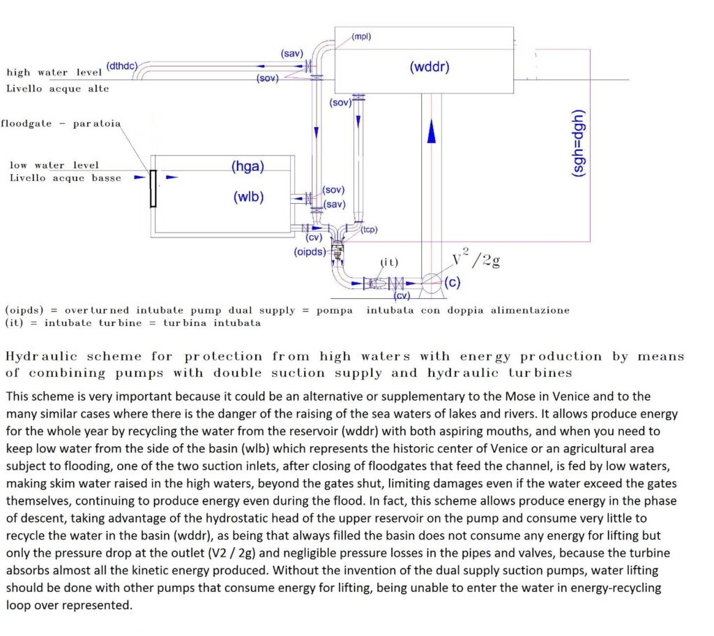
However, to make more versatile energy position of surface water and to use this energy in mobile systems it was also required the invention of the dual supply pumps on the suction side, which are the simplest invention of the undersigned. In fact, with this invention is fully closed the circle, showing that in addition to treatment plants worldwide, are also wrong lifting plants of water. Even the famous Moses of Venice, which cost 5.5 billion Euros and not yet functioning, could be designed differently: cheaper, more efficient, becoming, thanks to the invention of these pumps also energy producer. The absence of these pumps are easy to achieve with current technology, it has prevented the proper sustainable development of industrial, environmental, energetic. In fact, if they were born at the origin of the industrial age, probably, energy solutions summarized in this publication, they would make unnecessary the construction of large thermal plants; the transport of energy that wastes resources and pollutes; large pumps and large engines, which with new lift systems coupled to hydropower, not serve. The new hydroelectric power, if I’m right, can be produced everywhere, with yields tens or hundreds of times higher than the other energies, including fossil. This energy depends only on the energy potential possessed of the water that is used in recycling, without dams, large reservoirs and hydraulic jumps. Of course, even the solar and wind power cannot compete with the new hydroelectric, not only because they not ensure continuity of operation and therefore require energy storage systems, but because they can harness the energy of position or pressure, that ensure high yields. In addition, they use materials endangered and must take into account the costs of disposal and the environmental impact that produce in the environment. Unfortunately, even the obvious necessity of changing the pumps was greeted with silence by the manufacturers. They do not look to the new market would open but only to that which would be closed.
But we must also wonder why this simple pump, was not invented by insiders? For myself, the blame is always of the specializations. This modification could not be born by the test laboratories of the pumps, not even from tenders made by public offices, not even by multinational procurement, but from overall design of the plants that require technical creativity, that no one wants develop, preferring mono thematic applications, which not exceed their limits technological and scientific. It is necessary public plant applications multidisciplinary.
Unfortunately silences public and private show that no one is working in this direction. At least the design public should be able to put together with technical expertise, especially industrial, which cannot be acquired at universities. Today, the energy and environmental problems are faced with solutions always mono thematic, and plants are put together with the machines offered by the market. But machine manufacturers are experts in machine building, not in the design of facilities globally. Moreover, the concept of the word implant, when it comes to environmental problems must be much expanded because the facilities cannot be monothematic. The dog will continue forever to bite its tail if designers public does not learn to update the state of the global daily with working groups that meet on a daily basis, as is done in a large manufacturing company that produces a complex, high technology, as the automotive industry. Too bad that this industry, in a hundred twenty years has not noticed that would change also the power supply of the motors. This could be another challenge of the future: decrease at most mobile generator of hydroelectric power, increasing the pressure exercise of a compressible gas on incompressible water, without fuel, with autonomy of runs today inconceivable, if not resort to dangerous nuclear energy. But nuclear energy hardly may be mounted on vehicles. Of course it is also essential electronic technology developed for the control of the speed of electric motors, the aperture of the valves, the control of the pressures, but also this invention would not be possible without the dual supply pumps on the suction side, which will not allow the dispersion of the operating pressure, and not even water, which together will produce energy. But manufacturers of combustion engines are developing hybrid engines that reduce pollution, not eliminate, while electrical machinery involve large costs for the disposal of batteries, low power and little autonomy path. The half solutions could go well when no visible complete solutions were as pressurized hydropower Mobile.
Is there anyone in the world, public or private, with greater economic means of a retired person who wants to go against the tide? I think the world, so big, is being lost in a small glass of water, because serve only a few thousand dollars or Euros to test the basic principles of these inventions. If everything works, the industrialization can be done quickly in conditions of fair competition between all interested companies, giving to Caesar what is Caesar’s. It could also be a simple thank you. As Inventor I do not believe to the current rules on intellectual property, which has never protected the inventors but only industrialists, who can pay protection. Industrial property now seems designed on purpose to protect only multinationals and commercial products.
The real fathers of science and progress have been those who have studied solutions over the parts, even going against the current, as Aristotle, Archimedes, Galileo, Pascal, Newton, Einstein. The undersigned, cites, unworthily, these great men who have demonstrated, even before that the industrial development happened, without the support of industrial technologies and computer, that in the environment and in nature everything is connected with a precise logic, that probably not would never be found in modern society, where the research is motivated only by profit. Today, the genius of these great men, would be absorbed by a corporation and would never have done those very large discoveries motivated only by love for science. For practical purposes, especially environmental, discoveries of these great men are not used in their whole potential, because rarely, they have been used synergistically. The private profit has also taken over and scientific applications have been cut to slices, so that there exist lobby of the various types of energies and various types of purifications, which leave voids enormous, technical and legislative. No one realizes that in the whole world there is no set of systems connected rationally to complete cycles inorganic and inorganic left hanging from various human activities. But myself, who proposed, unsuccessfully, global purification systems, in this article wants to talk, especially of the new hydroelectric power, which is making an even more difficult path, not even getting the support of patent offices Aristotle in his “Physics” of the fourth century BC asserted that the natural state of bodies is the quiet, i.e. the absence of motion, and that any moving object tends to slow to a stop, unless it is forced to continue its movement. The figure shown below (extracted from Wikipedia) shows. The pendulum of Newton, consisting of several balls (usually five), which is used to illustrate the laws of conservation of quantity of motion and energy.
This simple experiment is an isolated system that demonstrates that with the passage of time, the friction with the air gradually dissipates the energy initially imparted to the beads. Consequently, the period of oscillation of the pendulums decreases progressively to lead to the arrest of the motion of the spheres. As Aristotle said it is necessary to provide energy to keep it moving. The problem of humanity, as well as cleansing, which as mentioned above, no one wants to seriously address, is also to clean energy, which serves to keep human activities in motion. Not even this problem want to deal seriously, if anyone wants to discuss new ways of producing hydropower offering myself, not only on the basis of theoretical knowledge, but also practical experience of designing and building site. I reported on the well-known and simple pendulum experiment, as the premise of a much broader discourse, not energy conservation, that is obvious, and i certainly not put it in question, but on the transformation of energy, which is another thing, much more important. In fact, the mechanical perpetual motion can not exist but the synergistic, multidisciplinary, including scientific principles, the technology applied to the hydraulic, mechanical, pneumatic, can exist even with very high yields, as I show in this publication.
Are not text the silences that I picked up on aspects purifying the environment and those who are collecting my recent inventions relating to hydropower, because many people cannot express their opinions freely, being bound by company policy public and private, also , very few have the experience necessary to cross the merits of these inventions. In fact, the comments received by the Patent Office, European and Italian, do not enter into the merits of the solutions They just accuse me of violating the principles of conservation of energy, as if they were divine laws.
These principles are designed for isolated systems, when there were no current technology and they, not only extend to multi-disciplinary systems, but also to the coupling of machines that exploit unlike in the past physical energies present to the state inertial in the air and water.
The second charge, always generic, is as follows: “the energy that is consumed is produced by the same system.” Even this is absurd remark because all the power plants of this world consume some of the energy they produce, including those using fuels. Probably, patent examiners intend to say that energy can be produced by means of fuel, biochemical processes, or kinetic energy due to wind and water gradients, while the gravitational forces, the static pressure of the air and water, are comparable to the nothingness. Nothingness cannot be transformed into energy.
This is at odds not only with what is shown by the undersigned in individual deposits patent with practical calculations, based on the principles of Newton, Bernoulli, Pascal. But my simple calculations are confirmed also by the general theory of relativity of Albert Einstein. Einstein expressed a modern vision of gravity, no longer seen as a force but because of the curvature of space on the moving bodies, confirmed by the spherical shape of the planets and the gradual layering of various gases that surround them, as concentric circles bound together by gravitational forces, with density decreasing from the center. The layers are not separated hermetically. If we have seven major densities, forming seven main spheres, within each of those densities are seven layers of sub-density, and within each sub-density there are seven layers of sub-density, and so on. Even the line between hydrosphere and the lower atmosphere (troposphere) is a flexible line and leaking that allows the transmission of chemical and physical energies. Suffice it to say the absorption of CO2 by the water which is becoming more acidic, but from the energy point of view, it is interesting to observe the winds that produce surface waves and below sea currents. The boundary line between the atmospheric gases compressible and incompressible water is an immense source of energy. In fact, the energy of water and air in the quiet state, are balanced on the surface layer of the water only because water is incompressible, but also being extremely flexible, as demonstrated by the ocean currents, is very suitable to the transformation of energy. The problem was to transform the kinetic energy into electricity. This problema can be solved by two ways:
- By channeling the spontaneous motion of the waves and fall from the top of the water by means of large civil engineering and electromechanical on piles of a hydraulic turbine.
- Considering the large volume of water available to us on the planet “Earth” strewn with large and small pressurized tanks of atmospheric pressure, within which we are able to artificially concentrate the energy of the air pressure and that of position of the water surface, at one point only, which is the impeller of a hydraulic turbine placed under the pump, using vertical intubation of water and putting pump at lower.
For the undersigned despite until today, it was only used the first solution, the second solution is much better that does not require large building works, one can carry everywhere, especially in artificial basins of any size. But with the change of pumps and systems, as specified below, you can produce energy even lifting the water in aqueducts, for environmental protection and even in a mobile version.
These solutions are not even been inspired by the general relativity that has inspired nuclear energy, important astronomical discoveries, it explained important gravitational phenomena that were not understood, but the men did not comprehend to improve hydropower born in 1870, which uses only the kinetic energy produced through hydraulic jump between two basins placed at different elevations and some breaking wave. For myself, general relativity is the most authoritative confirmation of the ability to produce electricity in the same volume of water, although it is easier to understand the other physical laws, unsuccessfully, cited in the patent applications and other publications of myself. The undersigned found no web publication that talks about the experiences made on the combination of pumps and turbines in line in the same descent of water, to overcome the state of inertia and focus the moving mass on poles of a turbine. This is confirmed even from research reports, received by the European Patent. Therefore, no one on earth has ever tried to harness the energy of the relative position between the surface and the underlying part of the same tank, reservoir, nature, sea, ocean, by means of intubation of the water and the combination in series of pumps and turbines. This energy no one has taken into account to a misinterpretation of the law on the conservation of mechanical energy. This law states that, in a field of conservative forces, in the motion of a body under the action of the forces of the field will keep the total energy, i.e. the sum of the kinetic energy and the potential energy. It ‘clear that this law refers to an isolated system it cannot be invoked in the case of the solutions that I propose.
This law does not explain the origin of the forces of the field that is the real problem to be solved, together with the system to maintain these forces over time. This law at the time in which it was conceived, could not foresee that by combining three elements, non-existent at the time, things would change completely: intubation vertical of surface water, a pump and a turbine in series to the bottom of the tube and in the same water basin, or in the vertical extension of the same without interruption.
With this simple system, by four money, we can solve one of the greatest mysteries of nature and create a flow of water, one-way, infinite, that during the descent exploits simultaneously, gravitational force, atmospheric pressure and the weight of water intubated, while the rise of water is not necessary, since the density of the water surface equal to the one below. So, the perpetual motion combined: hydraulic and mechanical it is possible consuming a small portion of the energy produced. The primary source is not oil, but energy cosmic Free, no one wants to use and experiment, this solution being challenged with the slanderous accusation of not respecting the principles of conservation of energy. It ‘a classic case of the ox that calls horned the donkey.
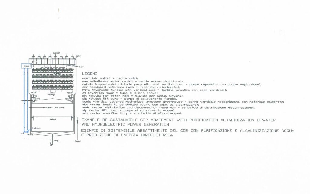
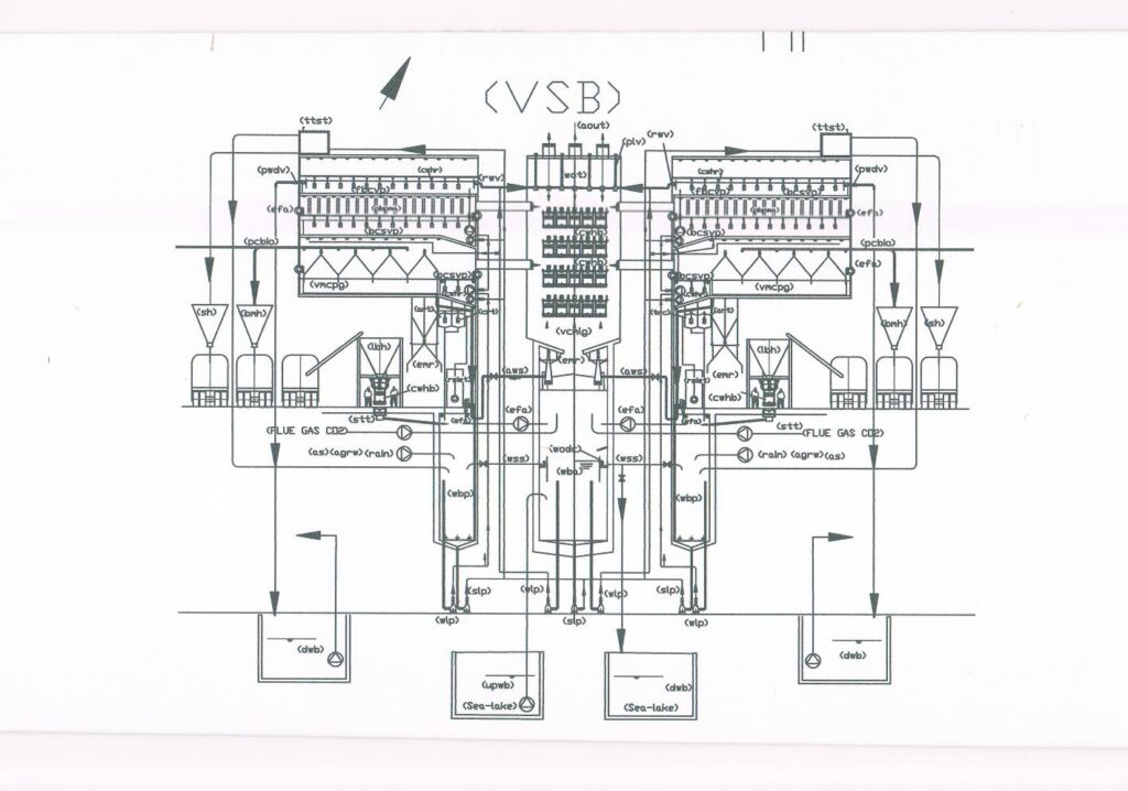
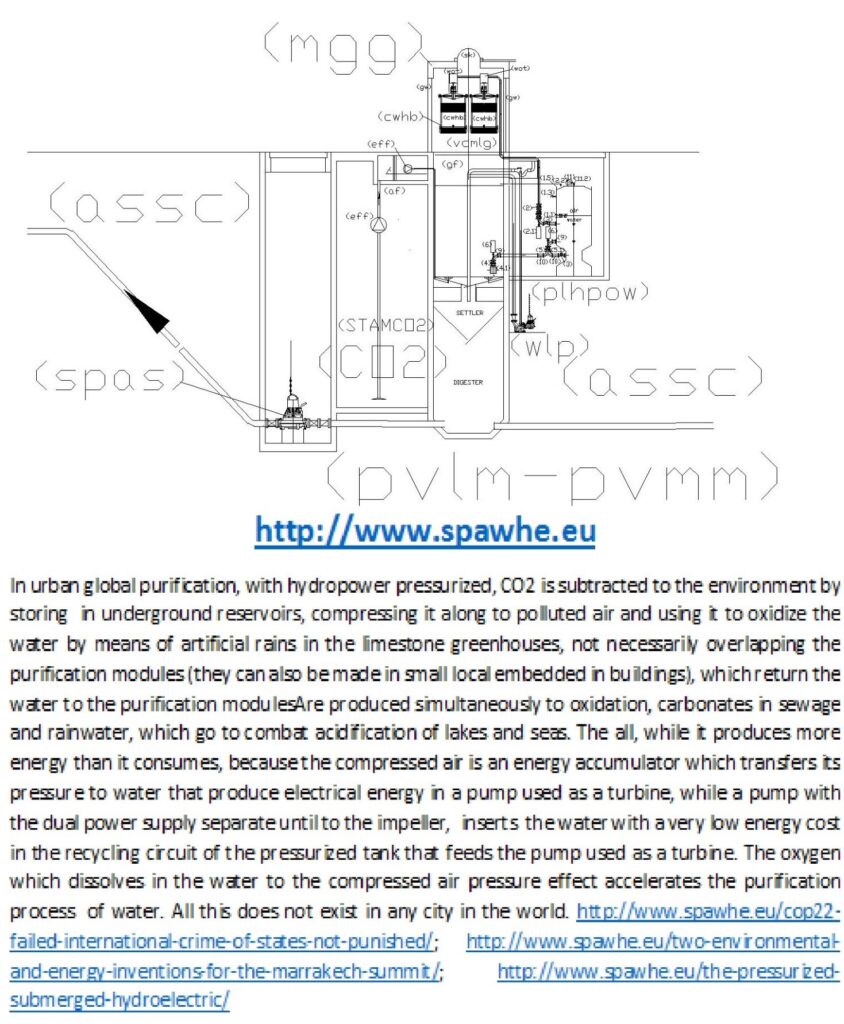
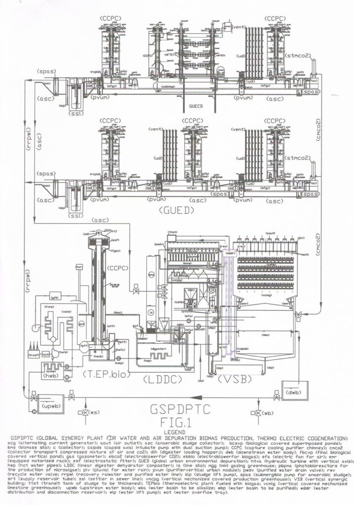
Those who respect the principles of conservation of energy? The ruling class worldwide with oil, shale gas, nuclear, or myself who has seen trashing thirty patents on environmental protection and sustainable energy alternative? Even when I have granted patents the result is not changed because no one wanted to invest. The reason is very simple: if the system is complex, although the recognition of the patent, no one realizes it because the legislature does not issue international norms that are binding on all (For example, to neutralize the CO2, or to not download acidic waters into water bodies: today laws allow download treated water with pH 5.5 and the CO2 and particulate matter in the atmosphere because the official art has not solved yet these problems, while the undersigned in 2012 has patented unnecessarily the neutralization of CO2 in greenhouses limestone that also would produce alkaline water and cut down part of the fine dust, if the system is also used in urban centers, v. pos. 6). Therefore, the patented system, surpassing the prior art is not competitive. It could become only in a subsequent phase, when the legislature intervenes, but the legislature does not intervene if he sees no at least one plant operated and the results of laboratory analysis of waters of the air. Under these conditions, the dog chasing its tail endlessly, because the invention was made by a private inventor who has no economic strength to take it forward. When it comes to installations of public utilities should intervene ministries of economic development, the environment, or the United Nations, but for unknown reasons they do not intervene.
As mentioned above, the undersigned, from experience, knows that getting the recognition of a patent, from a practical standpoint, it means nothing if no one finances, but as an independent inventor of environmental solutions and energy, he has the right, claims recognition of patents. The archive of patents is also important for the history of science. Who is right or wrong, sooner or later it will come out and will be outside the competence demonstrated by patent offices.
Whatever happens, I think at least for those who accept my reflections and my energy calculations, can finally understand where we can take the clean energy to start the motion and keep it in time.
Einstein understood and demonstrated that the principle of energy conservation involves both matter and energy. With general relativity, these two realities can be considered jointly, given that one can become the other according to a precise mathematical relationship, then the same matter can be transformed into energy, if we design and build the facilities where conditions are favorable for this transformation, or, before we make the necessary installation conditions and then start producing energy. Not only can we transform the kinetic energy of position into and from these into electricity, but also transferred to other systems, in the version artificially pressurized, as if it were derived from a fuel. In fact, even the first law of thermodynamics is a formulation of the principle of conservation of energy by stating that the energy of an isolated thermodynamic system does not create or destroy, but transformed, passing from one form to another. It ‘obvious that it is easier to produce thermal energy than physical because the latter, being able to be produced only by an energy of position, leads to higher dimensions also realizing an artificially pressurized version.
But The energy of position is more economical and clean the thermal energy and the possibility of reducing the dimensions of the mobile version, by means of the experiments are immense, if we consider that the pumps can arrive at pressures of 100 bar, consequently also the PAT (pumps used as turbines) and that in place of the compressed air may be used a gas that liquefies at a higher pressure.
I think that the world is being lost in a small glass of water because until these simple solutions will not be tested, it will difficult recognize practically where is hidden the physical potential energy that would eliminate the costs of drilling, refining, transportation, depuration, being an energy ready to use, especially clean. I do not know what happens in other countries, but in Italy the Patent Office, under the Ministry of Economic Development. It should be such a ministry to promote these experiments and finance them. Instead happen the contrary. I’m not talking about nuclear energy, fusion hot or cold, even for complex processes such as the transformation of hydrogen into fuel. I talk about clean energy ready to use, available to everyone, which requires only a few thousand Euros to experience it in the various solutions, at least to see who is right or wrong.
The technology it takes to accomplish what I propose is available at least half a century. But it is clear that these solutions are not convenient to anyone of those who mismanaged the energy solutions, on scientific economic, technical and political aspects, as has been useful biological energy, integrated in water purification and of urban air, which would eliminate the existing treatment plants, which is useful far from cities, that not purify well water, while urban air pollution is not purified but released into the environment from the occasional winds and rains. The new hydropower bothers the old and new energies, because no one could compete for cost-effectiveness and quality, as the global treatment given by the undersigned bother to current purifications because it means that are wrong, both purification systems, both for energy. If plants are wrong, they are wrong even the machines that produce private companies, despite having developed good technologies.
In fact, in industrial systems, until proven otherwise, the plants are designed to perform certain work cycles and machines must be used to run them. We cannot predict cycles that the machines cannot make and cannot be configured systems only with machines that the market offers. Those who design the facilities of public utility must be able to prepare the technical specifications to allow manufacturers to design and build the machines that serve, but this does not occur in public facilities. While in the big private industry manufacturing the machines are tailor-made for the client, there are even robots for welding, assembling, and coating. In fact, the pumps with dual power supply on the suction side, indispensable, for hydroelectric applications with recycle water in the versions fixed and mobile, still does not exist, no fault of those who build the pumps, but for those who design plants, which has never required.
This version of the pump the patent office has not yet expressed, but has already expressed the silence of the pump manufacturers, which prefer to continue to build multi-stage pumps consuming more energy, requiring for more powerful engines as long as the market does not require pumps that really need to save energy and sustainable energy production. With this involuntary connivance between public and private managers, it promotes a wrong model of development in which we earn only insiders public and private, while the environment, the real economy and the taxpayers who pay taxes loses.
Obviously, to move an inefficient system in the world, is not enough the details developed by a pensioner, though you can almost touch. This would be an opportunity for the opposition to oppose easy alternative proposals, even with experiments. But they, who also have sufficient funds, prefer to oppose only words, not projects. I refer trade unions, environmental groups, the churches, the poor and the common people who do not belong to the eleven million people that hold 75% of global wealth. The marginalized from the decision-making powers continue to delegate the 100% of the study of energy solutions and cleansing to the powerful of the earth who do not want to find them not to share more wealth equally. If things were not in this way, at least some of the solutions that I proposed would be tested. Environmental degradation, unemployment and the huge disparity between rich and poor is not only the fault of the powerful and the mafia but also of those who oppose only with tools of facade, without entering in the solutions details but only in the complaints. Instead, the war to the inefficiency must be combated detail by detail, without losing sight the overall objective, not political, but of the common welfare. In democratic regimes who governs must also experience alternative public utility projects of the opposition who do not have the funds, or technically justify the rejection. Not just the simple silence. If industrialization has produced something good, this thing is the technology, which if applied properly, would allow the construction of installations coherent with the environment. A plant cannot be interpreted as a philosophical treatise, it is made of details, based on the principles of hydraulic, pneumatic, electrical, already tried and tested. If it works or does not work must be demonstrated experimentally. No one can prevent the granting of a patent, an inventor who has no money for the trials, without saying what are the details that can not work, not on general principle but on physical laws, such as the compressibility of the gas, incompressibility of liquids, the principle of communicating vessels, the principle of Pascal, the Einstein’s general relativity.
Hydropower with the hydraulic jump does not violate the principle of conservation of energy because it uses the energy of position clear to all. But not even we can say that violates this principle who builds a facility a little more complex to exploit energy of position less accessible, but just as real, documented with simple hydraulic calculations (see other publications available on the website http: // www.spawhe.eu). In fact, the energy location not accessible can be transformed into kinetic energy by means of intubation of an aliquot of the water surface, of a machine (pump) which transforms it into kinetic energy and subsequently uses kinetic energy to produce energy electricity through the turbine with related alternator.
We cannot say that not even a regret that accomplishes these transformations produce energy from nothing because the gravitational forces, the hydrostatic pressure of the water is in inertial energy equilibrium. It is sufficient to break the balance in order to obtain a transfer of energy from one system to another. At this serves environmental design, not to put together machines that offers the market of multinationals. You cannot even say that the energy produced cannot exceed the return of 100% compared to the energy expenditure, because there are physical laws more favorable the stage of converting energy (downhill of water) and more parsimonious in the next phase (turbine output ), which does not involve energy expenditure, apart from the friction between the molecules (v2 / 2g) and the walls of a tank (if we are not in a large dock) which, however, does not involve the onus of the lifting of the water, acting in each case, in installations always filled, where the suction head and the pump delivery coincide. So, for the circulation of the water you do not have to win pressures but only the friction of the circuit. If you need to create a pressostatic imbalance, the pressure should be on the inlet pump, not on the delivery. I am sorry to say, but these things do not require testing, but only reflections, which unfortunately no one does and that the undersigned could do them only as a pensioner. All facilities that raise the water against the atmospheric pressure and gravitational forces are wrong energetically. For this reason, as I proposed in my patent, they should also be changed lifting plants and pumps.
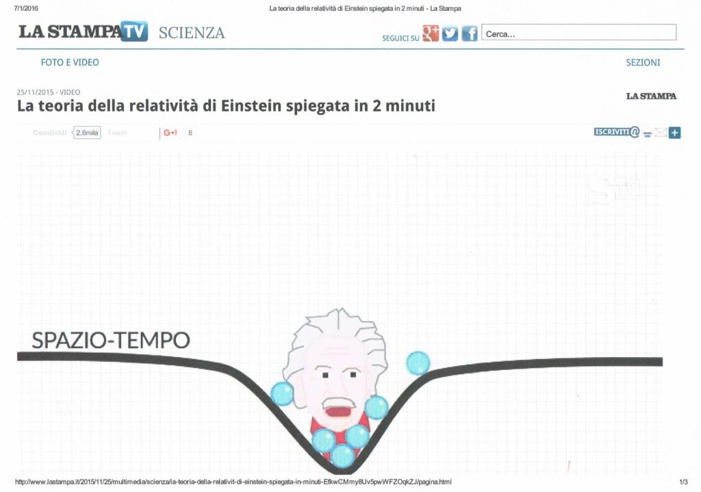
The formula E = mc2 by Einstein, who became the most famous in the world expressed in any reference system the total energy of a particle stationary with respect to that particular frame of reference. If the body is in motion, the formula becomes E = mg c2, where “m” is the mass relativistic, “g” is the coefficient of expansion, “c” is the velocity of the electron. This formula is very similar to that of Newton, concerning the transformation of potential energy into kinetic energy. But Einstein says that the energy provided it does not increase the speed of the body, but it’s mass: the body becomes more and more “heavy”. In space-time concept, which combines our classic notions traditionally distinct space and time into a single construct unique and homogeneous, many scientists have shown that what we call gravitational force has a curved shape that depends on the mass of the sun and planets but Einstein showed that the masses distort space-time in their vicinity, and other bodies move in trajectories determined by the geometry of space-time (for example wind). In other words, a concentration of matter bends space (and time) as an elastic membrane. In the black holes the time is slowed down to a great deal; It can assume that, at their core, the weather is completely stopped. This explains the densification of matter and the reasons for which the material becomes heavier. It makes Well l this concept the following figure published in a short video available online by the journal “La stampa tv scienza”.
For example, Einstein’s equations can say whether and under what conditions it is possible that the concentration of matter in the cosmos form a black hole, and what would happen in its surroundings.
But applying this concept to the terrestrial area, there are many phenomena which confirm that matter is transformed into energy when happen the alteration of the inertial balance for various reasons, as might be the passage of a comet in the vicinity, the potential differences between the clouds and the clouds and the earth, whose potential differences even produce immense electric shock. The same winds are air masses moving horizontally on the Earth’s surface, from areas of higher pressure to areas of lower pressure. The wind direction is influenced by the rotation of the earth. With the wind turbines we lay capture infinitesimal parts of this energy physics. For myself we can capture much more energy, if we ourselves break the balance of the inertial masses, where the conditions are more favorable, in particular, on the border between the atmosphere and any body of water with the system called by me “submerged hydroelectric “.
in fact, the insight of the undersigned, to create energy recalling from below the water surface by means of a pump upside down, is also confirmed from the point of view of Einstein well as that of Newton: with the concentration of a mass of water in the pipe down, we have only at the initial potential energy: E = U = m * g * h. If the mass of water moves due to a descending flow produced inside the tube from the pump, at the lower end, the entire mass of water contained in the tube, according to Einstein, the undersigned, Bernoulli’s theorem, the principle of newton (represented in the figure with the head of Einstein) moves downwards, dragging other particles from the water surface downward, becoming increasingly heavy, not fast, because the speed of the material, especially in the terrestrial environment has a very low limit: all the energy is dissipated as heat. But in our case this does not happen because the speed of the water is braking with the blades of a turbine and related alternator, producing hydropower infinity, with very low energy consumption, since the water, in plants always full, it is not dispersed , as in hydroelectric traditional and does not need to be raised to the upper level. In fact, since the level of suction and discharge of the pump coincide, the circuit ends at the turbine outlet. Having the same density throughout the basin, the water simply moves up and down and all the water that enters the descent tube is surface water that moves only horizontally until the entry of the tube, without lifting expenses against the gravitational forces.
For myself, this is the correct interpretation of the principle of conservation of energy, taking into account the state of the art machines developed, based not only on the general principles, which were forced to refer the fathers of science. These considerations also apply by simply applying Bernoulli’s theorem to the circuit submerged intubated, but to express the concept of Einstein, we can say that to awaken the energy existing in the context of any volume of water, we need to create a small black hole in this volume of water by means of the pump, by curving the boundary surface between the air and the water, with the aid of the pressure of the atmospheric air, and subsequently managing this energy by means of the turbine. Essentially, using the synergies between the intubation, the pumps and turbines can produce power indefinitely without fuel, using precisely the energy of position, the atmospheric pressure and the general gravity, the compressibility and the impalpability of water. These last two features become valuable when the exit of the turbine, the water with residual energy, it disperses in the static water surroundings, without undergoing the opposition of the hydrostatic pressure, which would suffer if it were not impalpable, incompressible and not had the same density. In fact, when we download fresh water in the seabed, it takes a slight increase in pressure drop at the outlet (V2 / 2g) in relation to the different specific weights (1025/1000), being more dense static water at the exit of the turbine. The water that comes out (lighter) slowly rising to the surface due to the buoyancy. But this does not happen in the cases which we will examine why we use water with the same density. Therefore, the water remains in the bottom of the basin, unless the basin is not of very small section compared to the water flow and the water is recycled in an open circuit (or closed), but in any case with the same level of water on the pump is suction and delivery. Therefore, in the new hydroelectric systems that I propose, you should never talk about energy costs for hydraulic lifting, but of minor or major loss in friction, which can always be compensated by the positive head on the pump, or the prevalence of the same. But in these systems, as mentioned above, you must never talk not even of the hydraulic counter pressure which for many people would prevent the water circulating in the descent tube to create the pressure drop necessary for production of energy. In fact, the phenomenon that produces energy in the turbine is not the pressure drop, but the energy transformation of the water surface position from the potential (m * g * h) to kinetic (1/2 * m * v2), which focused on the turbine blades causes its rotation. Without the intubation of a small part of the water of the basin and without positioning the pump in the bottom of the tube, does not exist the mass “m” and not even the position of height “h”. It exists only the gravitational acceleration “g” on the surface of the entire basin at inertial state, which, as said Einstein, in the presence of concentration of matter (caused by the rotation of the pump) bends the space (and time) as a membrane elastic. And in the specific case of a material as the impalpable water, incompressible, which takes the form of the reservoir that contains it, the elastic membrane, represented by the boundary line of the surface of the water and the atmospheric air, it immediately reassembles, ensuring the energy transformation for the whole period in which there exists the disturbance of the state of inertia (ie, until the pump supplies the turbine). This not only demonstrates that the static hydraulic pressure in basins full of water does not interfere with the internal kinetic energy to the volume of water, but also shows that the principles of the conservation of energy must be expanded also taking into account the physical characteristics of matter involved In transformations, and general characteristics of the system in which processing takes place. In fact, the Bernoulli law which summarizes the concept of conservation of energy of fluids, states that: “If the fluid is flowing in a conduit provided with a constriction in which V1 and V2 are the speeds, S1 and S2 are the respective surfaces of the sections, P1 and P2 manometric pressures measured in correspondence of those sections, for the principle of the conservation of energy is established the following relationship: P1 + P2 + = ½ d V12 V22 ½ d. The constancy of the value of the expression shows that, the greater the speed difference in the respective sections and the smaller the pressure difference, and vice versa. This law is valid both in the circulation of a liquid than a gas, but summarizes too the phenomena. In fact, the energy different behavior between a flowing fluid and another it can be seen only creating systems that are more complete. In fact, the gases are compressible and the fluids are incompressible, as shown, in this publication, taking advantage of these features we can write other pages on energy transformation, which were not written by scientists, who have used Einstein’s theories to develop energies, which still have to start from scratch to transform matter (sometimes radioactive). Not realizing that the same laws can also be used for applications much more practical, which would allow us not to start from scratch, taking advantage of the gravitational force, energy, water and air pressure position (natural and artificial). Over all, this interpretation, more complete, is confirmed by the same laws of physics exist: communicating vessels, principle of Pascal, Bernoulli, Newton, Venturi, Torricelli, etc.
On the other hand, the same energy produced by the hydraulic jump to the atmospheric pressure, uses the principle of Newton, which is very similar to that of Einstein, but there is no needs a pump to overcome the state of inertia of the water position. To harness the energy of the water position contained in a upper basin (m * g * h) just open a gate and water in the outlet pipe acquires a speed proportional to the mass that comes in and the height of the swing “h”, independent of the mass present in the entire basin. Also in this case, if there were not the turbines, all the kinetic energy would be dispersed into heat in the tubes of descent and at the outlet. However, it has been over 150 years since the invention of the turbines, and no one has ever thought to harness the energy of the relative position of the surface water compared to those below, just for the fact that this energy is less flashy. Yet it, around 1640 Torricelli published his law that shows without any doubt the existence of this energy: “the speed of a fluid flowing out from a hole (of very small section compared to the size of the container) is equal to the root square of the double the acceleration of gravity and the distance “h” product between the free surface of the fluid and the center of the hole that has been practiced: v = √(2gh). In other words, the speed is equal to that that would have the fluid during a free fall from the height “h”. In our case, the pump-mail to the depth “h” by moving the liquid below, produces the same effect as Torricelli’s hole, but with the advantage that the tank is not emptied and produce energy in the turbine with the kinetic energy acquired by ‘ surface water that falls within the vertical pipe.
2.1) Other reflections on the production of hydroelectric energy without the hydraulic jump.
The water is almost impalpable as the air, but has a density almost one thousand times higher. The air is compressible, while water is incompressible. The motion of bodies in the water and in the air is very different, according to their gravity related to water or air. The same movement of fluids, while following the same laws in proportion to the large difference in density viscosity etc., differs a great deal if you compare the compressibility factor and compressibility. For myself the water is the most powerful means of energy production for the features it has and also for the great abundance exists on the planet. It does not need to be exploited and hydraulic jump in combination with compressed air could provide pleasant surprises.
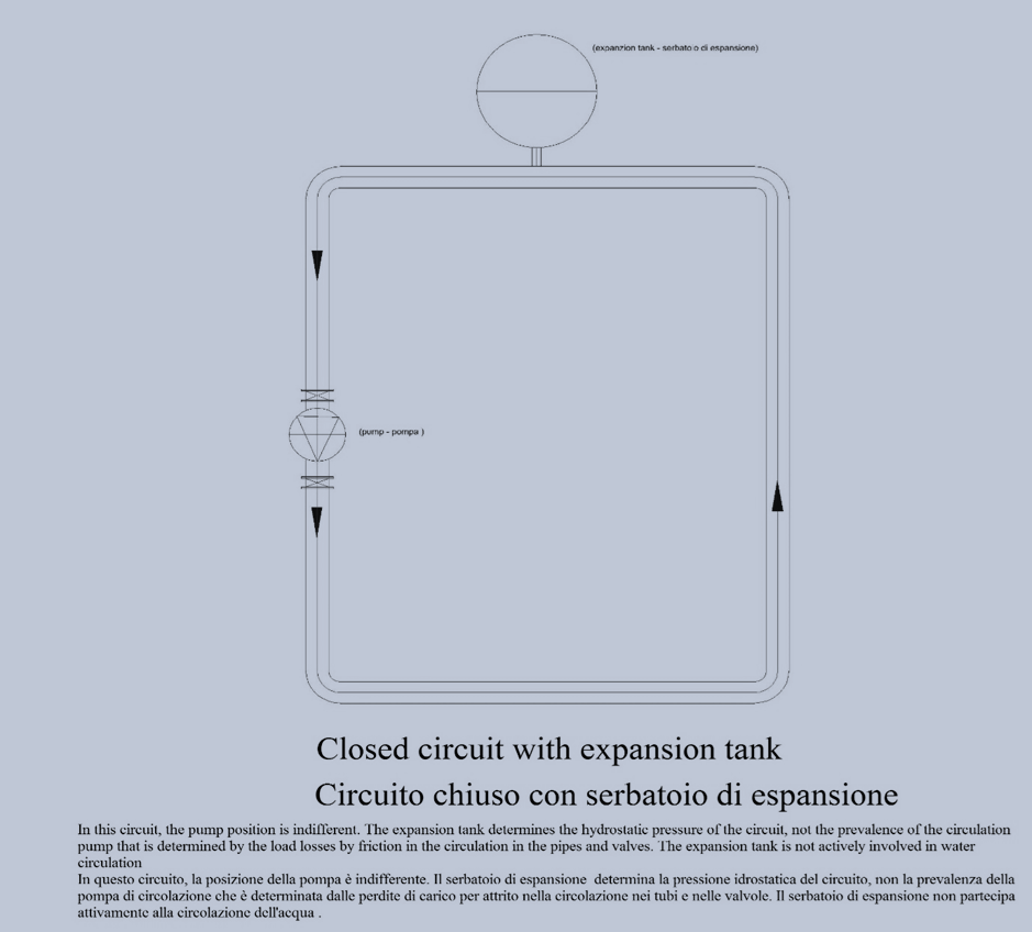
But, we start with the reflections, on the most simple circuits such as the one hereinafter reported, which is a simple recycling circuit with an expansion tank. This circuit cannot be turned to advantage in a power circuit because it cannot use any water position energy, so if we use a turbine would produce less energy than it consumes the pump.
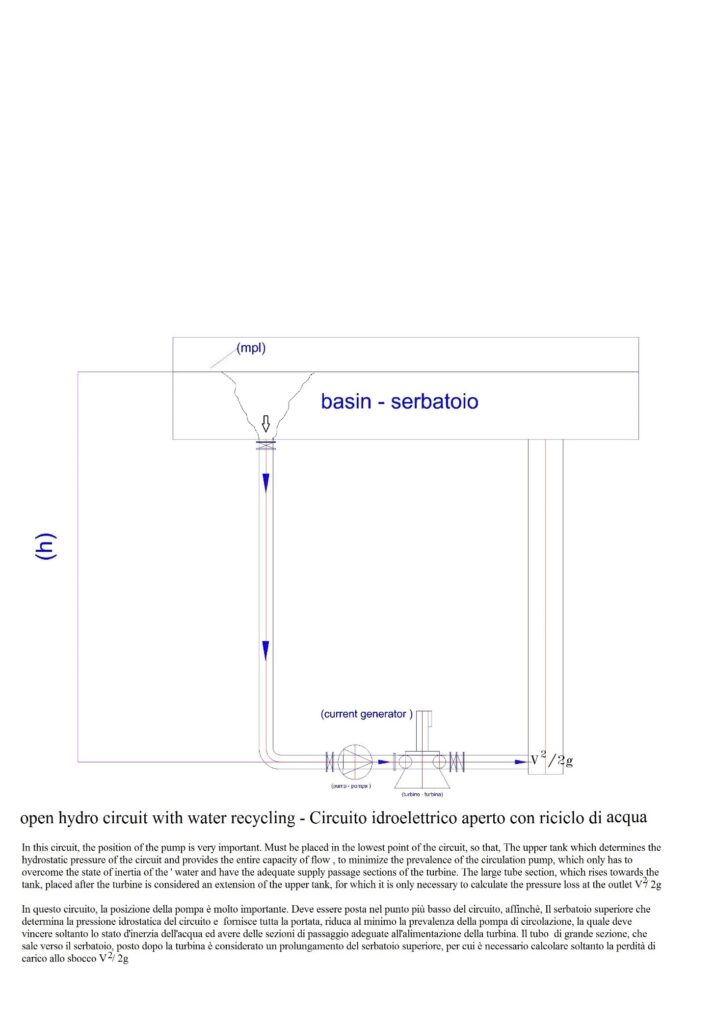
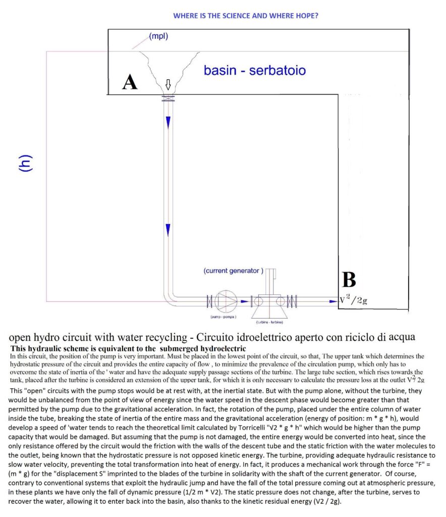
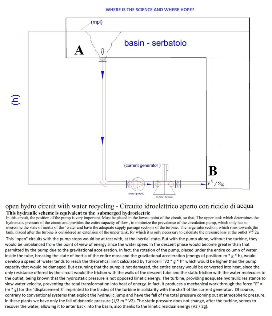
The drawing below, instead, we can assume a hydroelectric production, with water recycling, with an energy efficiency almost equal to that without recycling, respecting the known hydraulic principles, but also exploiting the gravitational force (one-way on the pump to recycling) and the incompressibility and the intangibility of water, which allows the reintegration in the water volume of the upper reservoir, without the opposition of the hydrostatic pressure of the same basin.
In fact, whereas the descent of the water caused by the pump which feeds the turbine, we must consider that with this system we obtain the same effect of the fall by gravity, since the turbine weighs equally a mass of water in motion that would acquire a remarkable speed dissipating all energy into heat in the tubes and the outlet, if it was not the same turbine alternator to produce electricity instead of heat. The only difference is that the traditional energy takes place only by gravity while the submerged is conditioned by the rotation of the pump, as explained in the same schema, absorbs very little energy. In fact, in the environment of restricted descent tube, if the masses are equal, descending in the direction of the gravitational force, increase in the same way its own weight, irrespective of the cause which produces the movement. The electrical power produced by the turbine-alternator, is calculated in the same way: (flow rate * h * efficiency = Kw (minus Kw absorbed by the pump). While, there is not much difference between an outlet into the atmosphere and submerged, water to equal output speed (V2 / 2g).
Of course, are important the following factors:
1) The volumes of water accumulated in the basin must be well above the water recycled. To not be accused to realize the perpetual motion we must draw energy from a superior system that possesses a greater amount than that which we need, but to inertial state. In fact, according to Einstein’s theory, the vertical tube placed in the bottom of the tank, by the suction effect of the pump, produces a small black hole that deforms the elastic surface of the boundary line between water and troposphere and the material falls into the tube with a speed that depends on the capacity of the pump.
2) The passage sections, the pipe and the pump must have the suitable size to transmit the entire hydrostatic pressure needed to reach (h = unit pressure * section) ensure that, taking, into account the yield, you get the power delivered by the turbine. (Q * H * ȵ).
3) At the exit of the turbine we must have an expansion of the section to simulate the submerged outlet, where water makes the most of the characteristics of compressibility and intangibility that allow it to take the form of the tank that contains with minimum expenditure energy, even if the outlet takes place in a deep extension, similar to a pipe. Therefore, does not exist, no geodetic height difference between the inlet and outlet of the pump downstream of the turbine, the water must not be raised from the pump. Once entered in the extension of the tank, paid the expense of pressure drop at the outlet, the hydraulic circuit and energy is concluded. The hydrostatic pressure at the outlet of the turbine exists but cannot oppose the residual kinetic energy that comes out of the same.
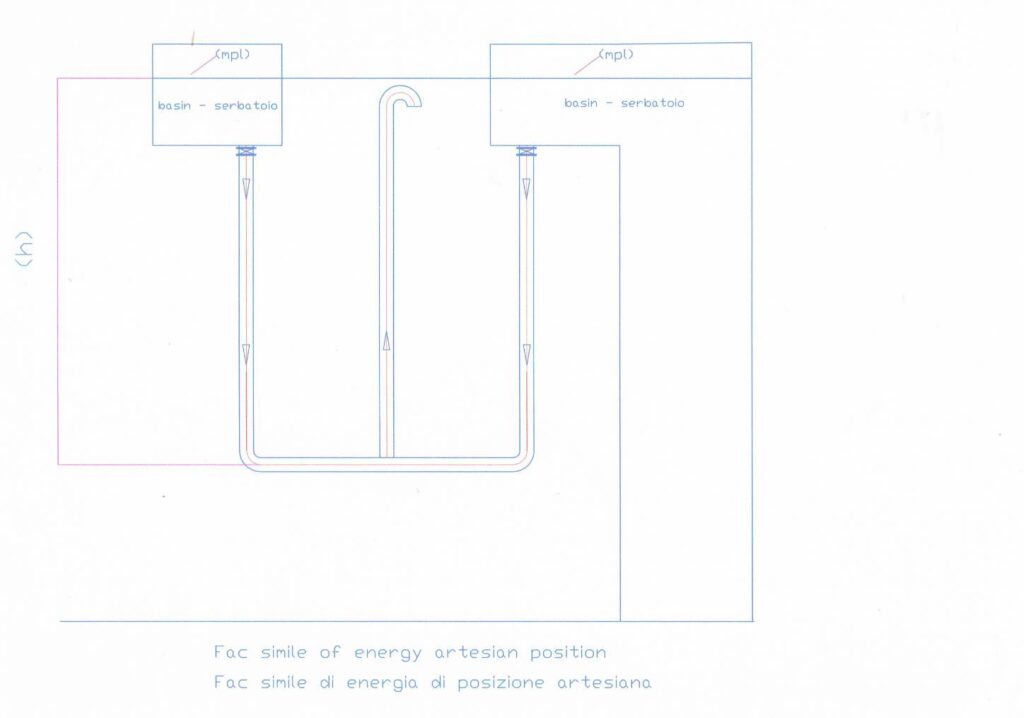
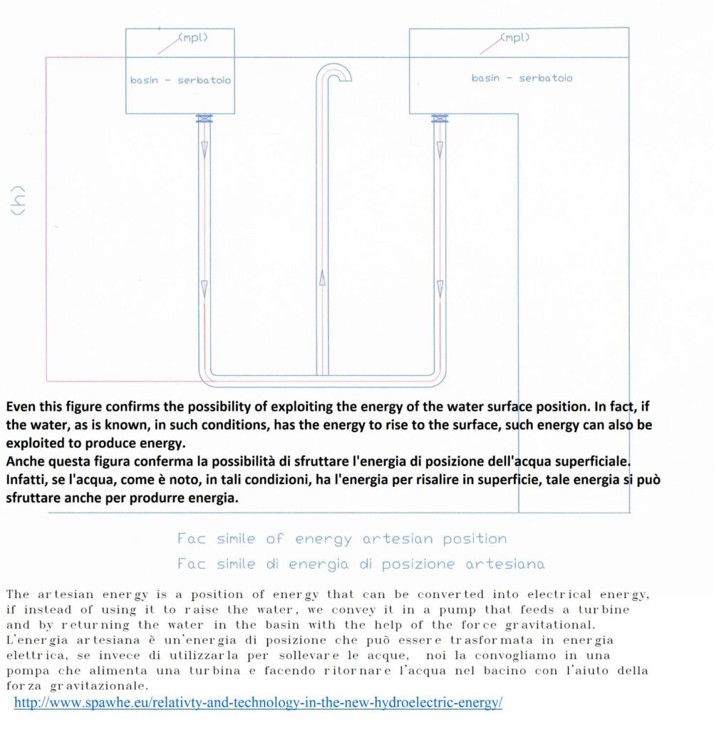
The figure above shows a facsimile of the energy position that takes its cue from artesian wells, which allow the lifting of water by intercepting a vein of underground water that connects two reservoirs. The flow coming out, without energy consumption, by the central tube which connects the two basins depends on the pipe diameter and the height “h” according to precise hydraulic calculations. This hydraulic condition artificially created is very exploited for the purpose of water distribution but is not exploited for the purpose of production of electrical energy, for the fact that it has not been taken into account a different use of the pumps and the hydraulic turbines and the characteristic incompressibility water.
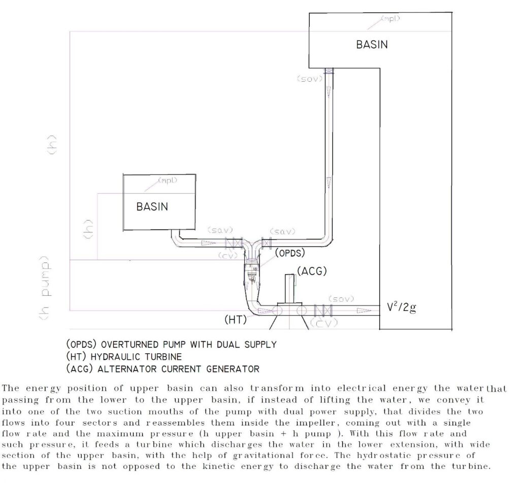
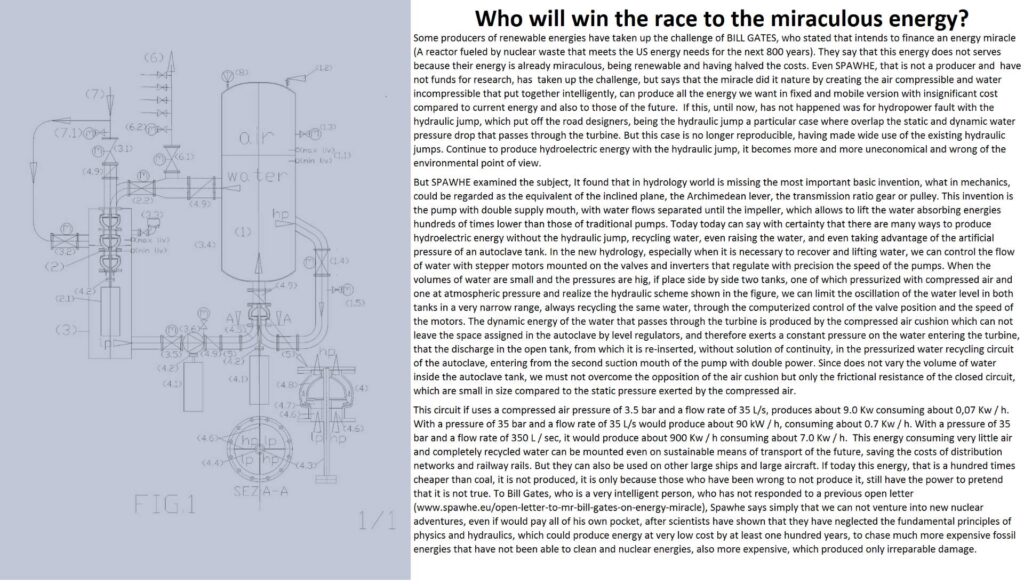
The figure below shows how you could use the energy of position of the shallow water (without the hydraulic jump) to produce energy instead of raising the surface waters by means of a pump that increases the water flow rate and the pressure, taking advantage the severity of the water column intubated and therefore, focusing the energy on the blades of a turbine, which produces electric energy. In fact, the static energy released by the drilling of the connecting pipe (m*g*h + ½ m v2 = costant) between the two basins and that supplied by the pump and by the gravitational force, liberated by the rupture of the state of inertia caused by the same pump, if not produce mechanical energy with the lifting of the water, as represented in the above figure, and even electrical energy by means of a turbine, as shown in the figure below, they can produce only heat to the friction with the atmospheric air which would be dispersed in the water, or with the water molecules, if the water is re-inserted back into the basin without the reduction of the speed that would produce the turbine. In fact, the water, in contrast to those found on the contrary, can be reinserted into the reservoir even in the presence of high hydrostatic flying because the hydrostatic pressure is not opposed to the kinetic energy, but with the classic loss of load at the outlet (V2/2g).
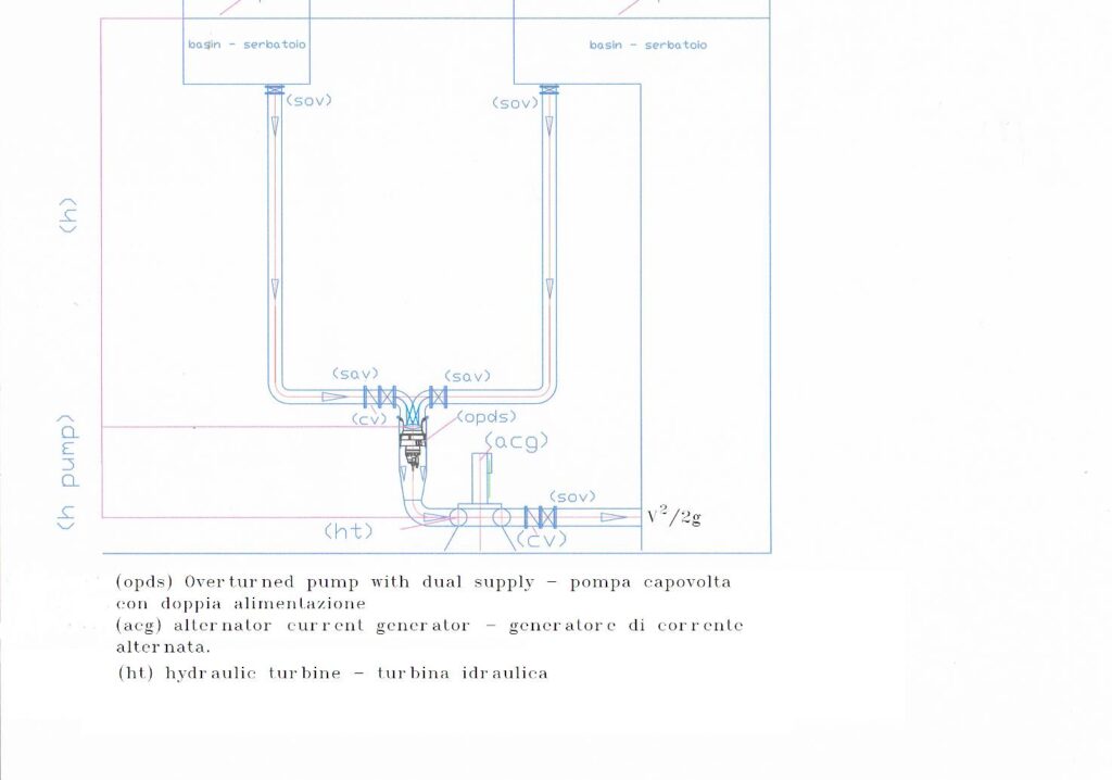
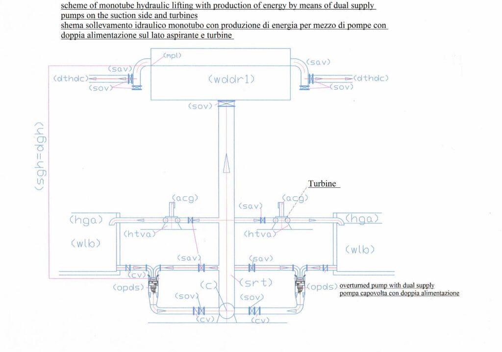
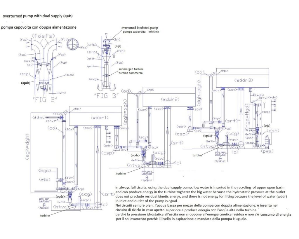
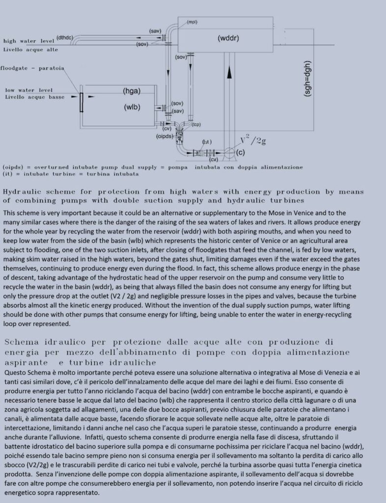
The figure below instead explains the reasons why we have entered into a scheme with the double feed pump on the suction side (which does not exist in the current state of the art). In fact, it can be noted that the water basin on the left side has been lowered, therefore, the pump enters the two flow of water with different pressures. The details of how they are internally pumps made are described in the chapter in which we talk about the change of the pumps, at this stage it is enough to say that with this pump, you can mix the water in the pump and come out with the sum of the flow and pressure provided both by the position of the surface water of the highest basin. If the passage sections are adequate to transmit the entire pressure also at the waters with less pressure, since the thrust force is equal to the unit pressure to the section, we can produce energy also lifting the water from the basin bottom to the upper, for the simple fact, that the water, does not need to be raised for two reasons:
1) Because the water level in the aspiration and delivery is the same;
2) Being equal to the density in the basin is sufficient to only insert it at any point of the volume of the basin or of an extension of assimilable wide section, at the same, since the water takes the size of the reservoir that contains it with the minimum expenditure of energy , not chargeable to external forces.
This system, not only is the absolute best for the production of energy is also the best for surface water management, requiring no mountain water accumulations that produce floods and even extractions of water from aquifers that are enriching of heavy metals such as arsenic. The continuous water circulation ensures constant oxidation and therefore producing energy, we can distribute water for drinking, irrigation, purification and even retaining the shallow water where high waters are a danger to people and crops.
However, these concepts will be also reflected in the chapter in which we speak of changes of lifting equipment.
The silence on this issue by the experts, especially in science, are very serious because in existing plants intubation water upstream of the turbine is already done. This is the indispensable condition for the water carries on weight force on the piles of the turbine, therefore, in a system full of water, where there is a state of inertia, simply inserting a simple pump with a very low prevalence, before the turbine. It is not true that this system can only transform into energy the prevalence of pump. On the pump acts the entire water column and until proven otherwise, in all calculations the hydraulic positive head to the pump must be removed from the head necessary for the lifting of the waters. If this were not true in Torricelli’s formula would not enter the height h that covers just the distance of the surface water from the point of kinetic energy levy, and until proven otherwise, in all the hydraulic calculations the positive head to the pump must be removed from the plant prevalence calculated for water lifting. But in this case must not be raised because the hydraulic circuit ends at the turbine outlet with an outlet in an open vessel, which is independent of the depth of the outlet, but depends only by the output speed (V2 / 2g), which is just slowed down by the turbine, as it happen in the case of hydro power plants realized at the atmospheric pressure. The back-pressure hydraulic at the exit of turbine is apparent, not real, since water is incompressible. The hydrostatic pressures are balanced but the total pressure is greater from the side of the turbine and the residual kinetic energy must overcome only the friction between the molecules. In the same way as in an outlet in air we must overcome the friction with the air molecules.
In essence, the current hydrology applying the principle of conservation of energy in small details such as the variations of the sections, rightly stating that a decrease in speed corresponds to an increase in pressure and vice versa but is lost in complete plants, using water as a burden to be exploited to produce energy and to be lifted to distribute water and defend the territory. Unfortunately, the second part of hydrology, which raises the water is against the conservation of energy, because the water in the liquid version, is impalpable, indivisible, and incompressible and assumes the shape of the reservoir that contains it, therefore, in tanks always full, the water does not absorb energy for lifting, not needing to be raised, but at the same time, if intubated, separated from the surrounding waters, can assert its own weight, as current in hydroelectric, which takes place at atmospheric pressure. The only difference lies in the fact that it is necessary to insert a pump that feeds the turbine, not to create pressure but only break the inertial balance mentioned Einstein. Obviously, the hydraulic scheme of always filled basin can be realized in many versions, both to lift the water, both to generate energy, one of which, even in the pressurized mobile version, that could replace thermal engines. Therefore, this erroneous interpretation of the principles of conservation of energy has affected the entire industrial and environmental development of the planet “Earth”. Must be the world’s environmental authorities to establish this truth, stopping immediately the wasteful energy for water lifting and production of expensive and polluting energy.
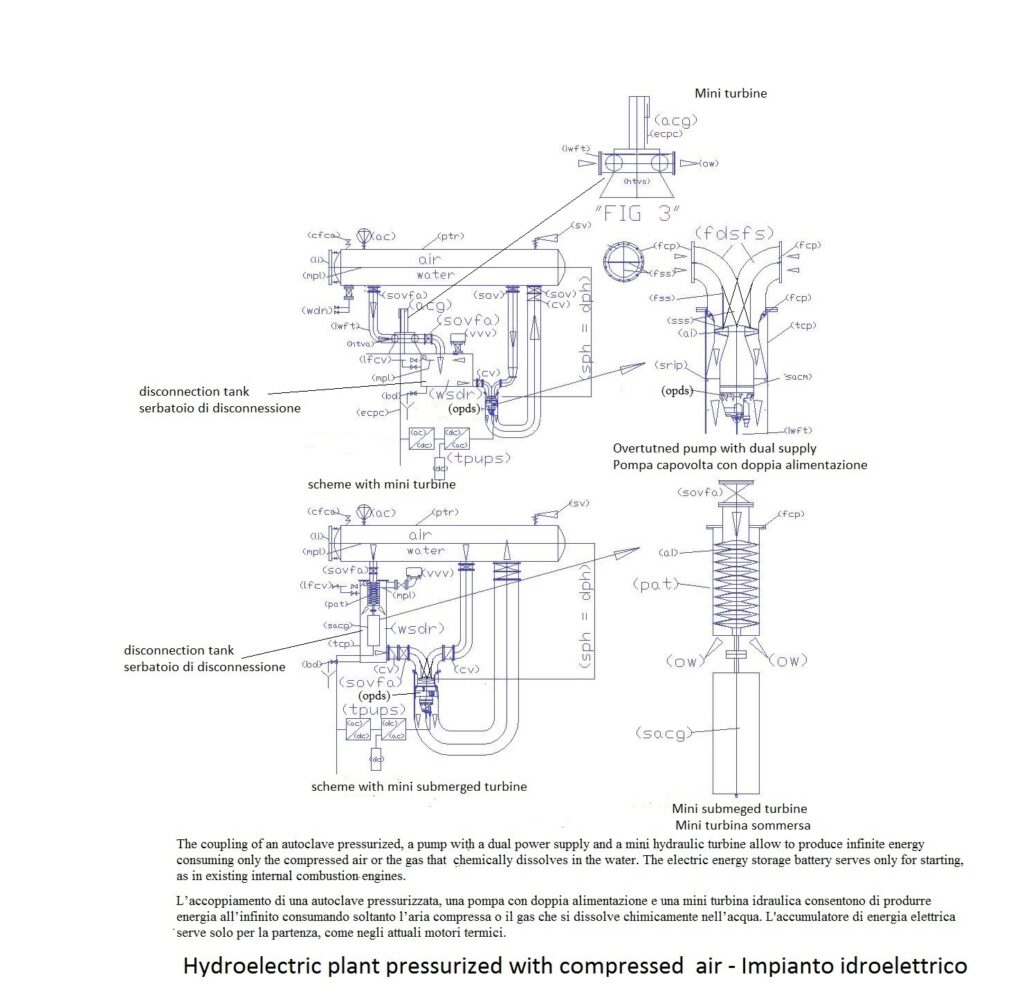
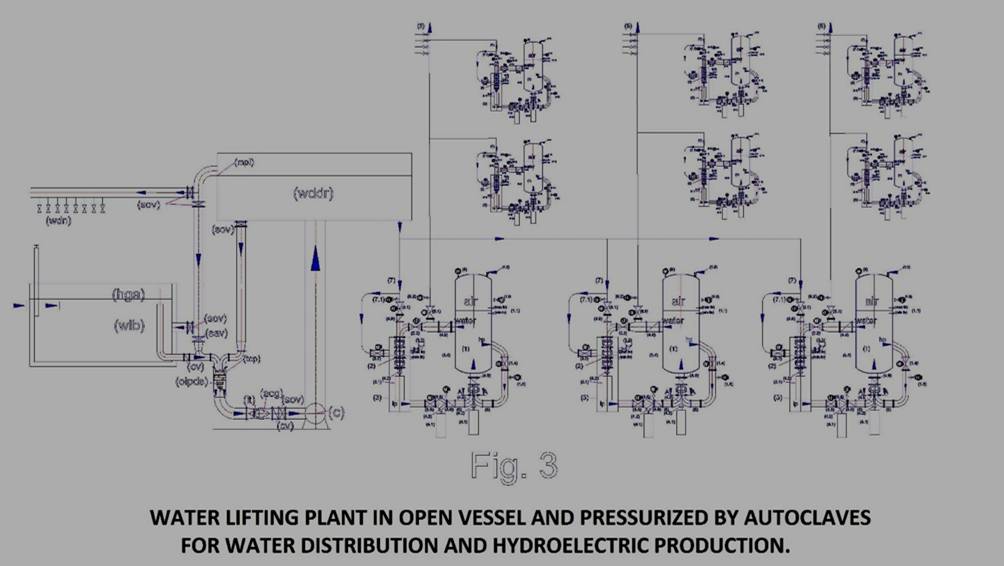
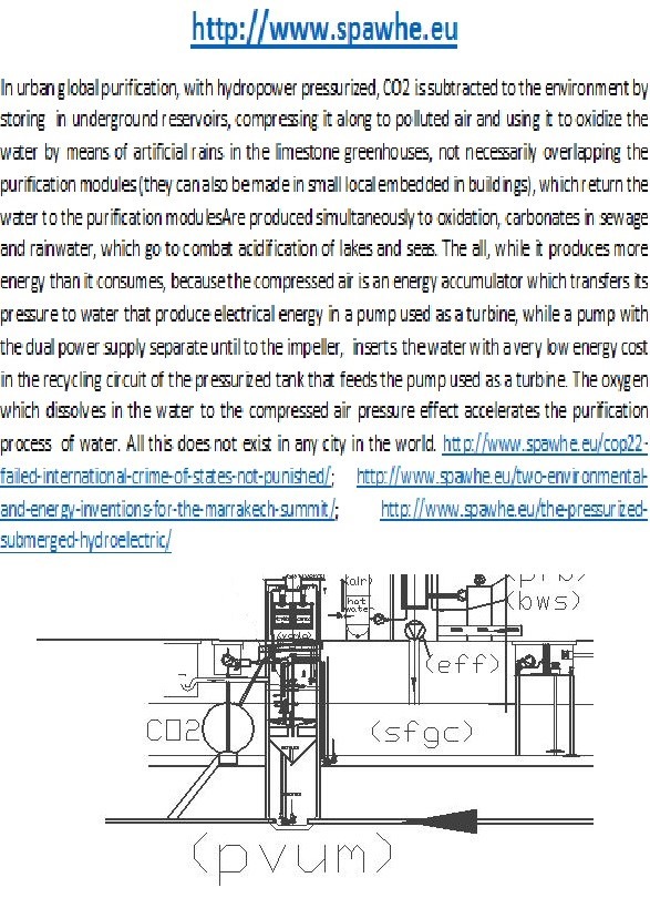
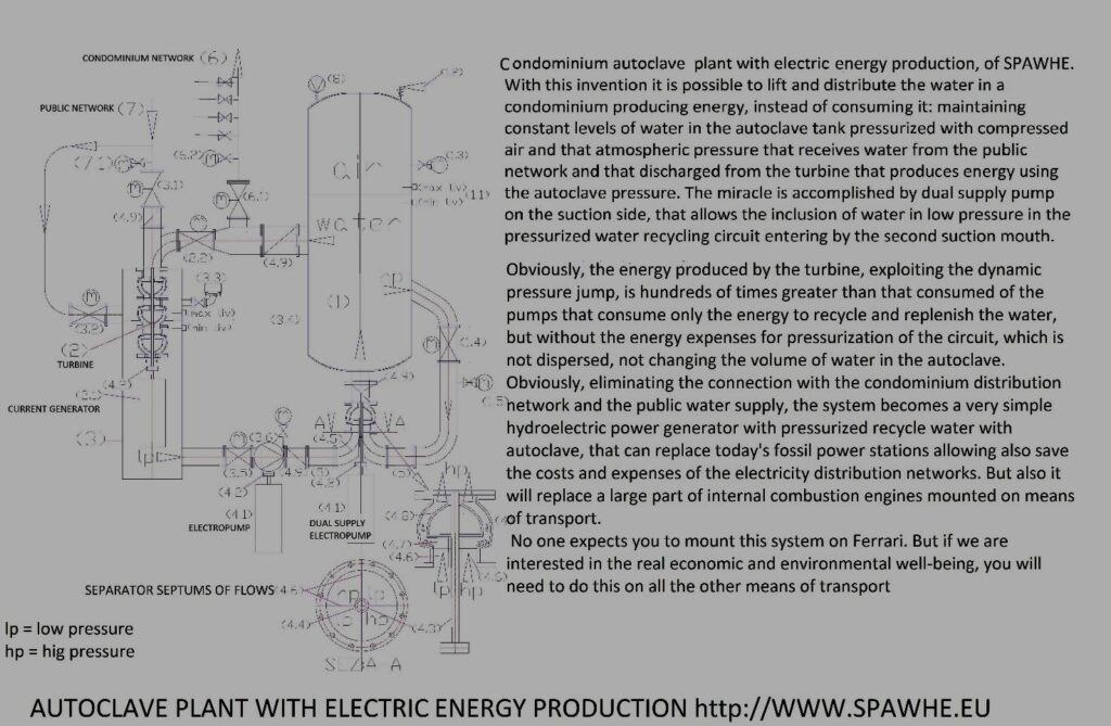
The following figure shows the connection of water and compressed air characteristics to the goals of energy production using the same design criteria.
This system will be described in detail in chapter “9”.
- SUBMERGED HYDROECECTRIC PLANTS
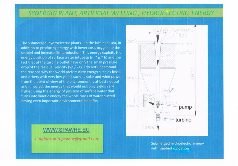
Assuming to provide a submerged hydroelectric plant and that the overall performance of the turbine and current generator coupled to both 0.8. The useful power can be supplied by a turbine which uses entirely the payload Hu than 50 m, intubated with a pump which has a flow rate of 1 m3/s, will be Pu = Q * η * 1000 * Hu / 102 = 0.8 * 1000 * 1 * 50/102 = 392 kW; while for rotating the pump in the conditions of balance between the positive head and the turbine dimensioned exactly for the same load we must overcome only the losses of load in descent tube. If this tube is the diameter 1000, and is 50 m long, we can take the load losses in the table on chapter 6, realizing that with the range 16, are only 0.0745 m (1.49 * 50/1000), by the same table we see that the speed of the water in the tube is 1.27 m / s, so the pressure drop at the outlet is 0.08 m (1.272 / 2 * 9.91). Also calculating the loss at the inlet with a reduction with coefficient 0.5 respect to the outlet, we have another small loss of load of 0.04 m. The total pressure drop is about 0.2 m (0,0745+ 0,08+ 0.04), so the power consumption of the electric pump, assuming the yield equal to 0,7 is 2.8 KW (1000 * 0.2 / 102 * 0.7). As we see the relate between energy produced and energy used is 140 (392 / 2.8).
Why should we be surprised by this amazing result? We do not know that even with the current applications that use hydraulic jump we have the same returns? Without consuming energy to run the pump? In fact this is the only advantage of hydropower with the hydraulic jump respect to hydropower submerged. In both cases, if there was not the turbine speed increase together with the load losses with an exponential curve, until it reaches a point of equilibrium, transforming all the energy into heat. Instead, the benefits of hydropower submerged are many: you can create it anywhere, it not disperses the water, it does not require large dams and large reservoirs.
The figure below shows a submerged hydroelectric plant in the sea or lake, as above descript.
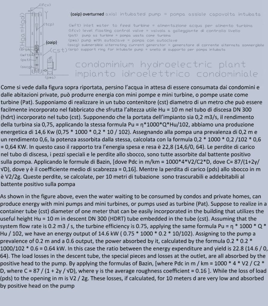
The next figure, shows the same solution in a probable future condominium plant, where the solution does not change although the volume of water is much lower, as the water level of the basin is maintained constant by the automatic topping up with water by means of a float valve. The water forced circulation, influenced by the swing of the pump is exhausted at the exit of the turbine with the pressure loss at the outlet. The water ski (in a passage section much larger) is due to the principle of communicating vessels.
This solution, in addition to producing energy at lower cost than other energy: thermal, solar, wind, would also ensure a continuous recycling of drinking water consumption, which today, accumulates in the collecting tanks that feed autoclaves, producing sludge and bacteria.
4) HYDROELECTRIC COMBINED WITH EXTRACTION PLANT FOR NUTRIENTS AND CARBONATES (ARTIFICIAL UPWELLING) TO COMBAT ACIDIFICATION OCEANIC AND CREATE HUMAN FOOD.
The state of art in the exploitation of marine resources has been conditioned by the hard access to the deep of the seabed. The phenomenon of the descending and ascending marine currents, known as “down and upwelling”, (where it happens) produces wealth and well-being even though, unfortunately, it happens naturally in a very small part of the world, because it need that many factors have to coincide like the intensity of winds and their direction or the structure of the continental slope. Some scientists have tried to fertilize the oceans by using iron sulphate that improve the phitoplancton production but the experiments, in addition to being expensive, presented many ethical, biological and sanitary implications due to the toxicity that this product may cause in the marine environment (fish production). The solution that we propose it is the ideal one because it plays artificially the natural system. By using unsinkable floating systems and a right interpretation of hydraulic principles like, for example, the communicating vessels, the Bernoulli theorem, the Venturi pumps, we can create and re-produce this phenomenon in all the waters of the world that, like we know, occupy three quarters of the planet’s surface. These plants are characterized by pipes that descend vertically UNDER the compensation line of carbonates (Carbonate Compensation Depth line), where the carbon and the carbonates are solubilized by very high pressures in the waters that dominate the oceanic flats. In any case, in the upper part of the descending pipe, it is mounted an electric, axial and ducted pump that works simply resting on a steel ring weld, under which, as submerged hydroelectric, is installed a hydraulic turbine. With the residual hydraulic pressure at the outlet of the turbine, realizing, near the seabed, some bottlenecks that suck a portion of the fluid from the outside (without moving mechanical parts they can work also in pressures condition over 600 bar), we can suck and mix to the water that rise to the surface the inorganic carbon, the carbonates and other elements dissolved in the water. These elements, on surface, with the atmospheric pressure, regain the low solubility that characterize the sea salts ad, overall, are at the origin of the formation of the calcium hydrogen carbonate that exists only in solution. CO2(g) + H2O + CaCO3(s) ↔ Ca(HCO3)2. The calcium hydrogen carbonat in the ionic form is written as follows: Ca2+ + 2HCO3– (calcium + carbonic acid). The balance between the CO2 dissolved and the calcium carbonate it’s the main element that determines the alkalinity, the PH and the concentration of calcium dissolved (Ca2+) from the fishes draw the necessary calcium for the formation of skeletons and shells in addition to the survival of coral reefs. In fact, when CO2 is in excess respect of the calcium, it dissolves in water to produce carbonic acid (CO2 + H2O ↔ H2CO3) leading ocean acidification and the extinction of fish species that are most in need of shells and skeletons. Since the advent of the industrial era, the sea has gone from a PH of 8.1 to the current average of 8.25. Since this is a logarithmic curve, this loss corresponds to a loss of alkalinity of 30%, which already is the cause of the disappearance of many species of fish and most of the coral reefs.
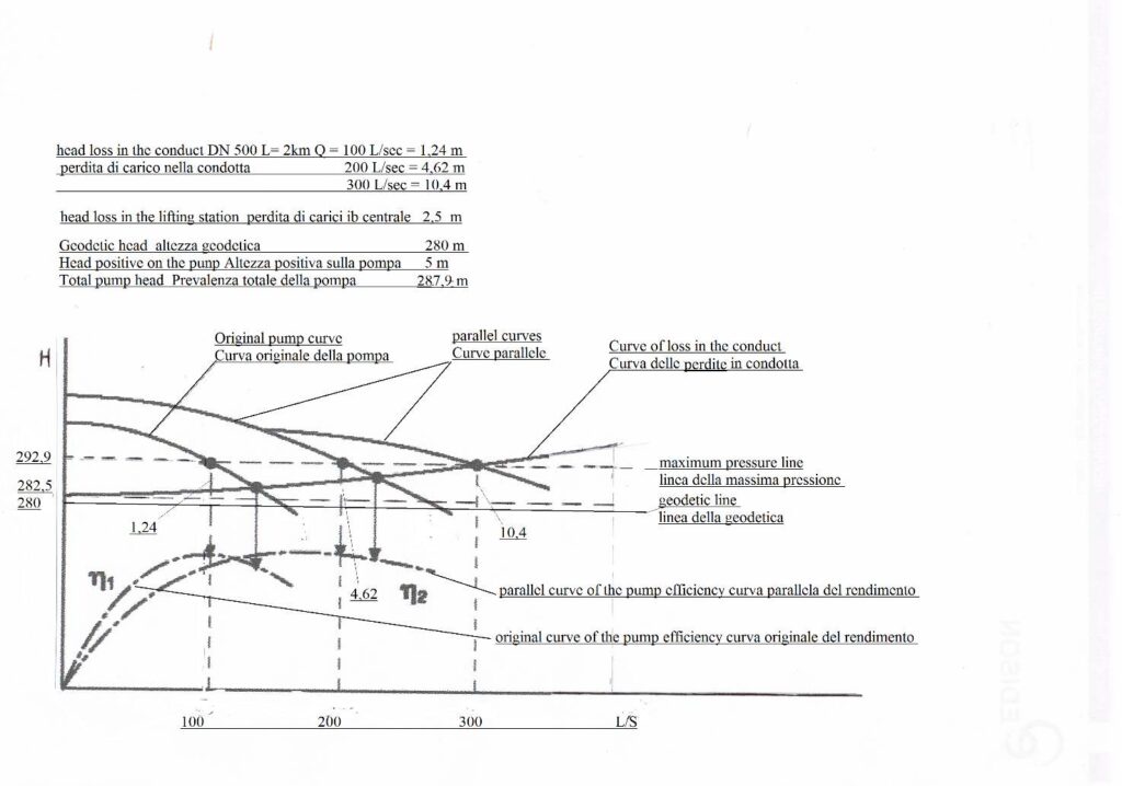
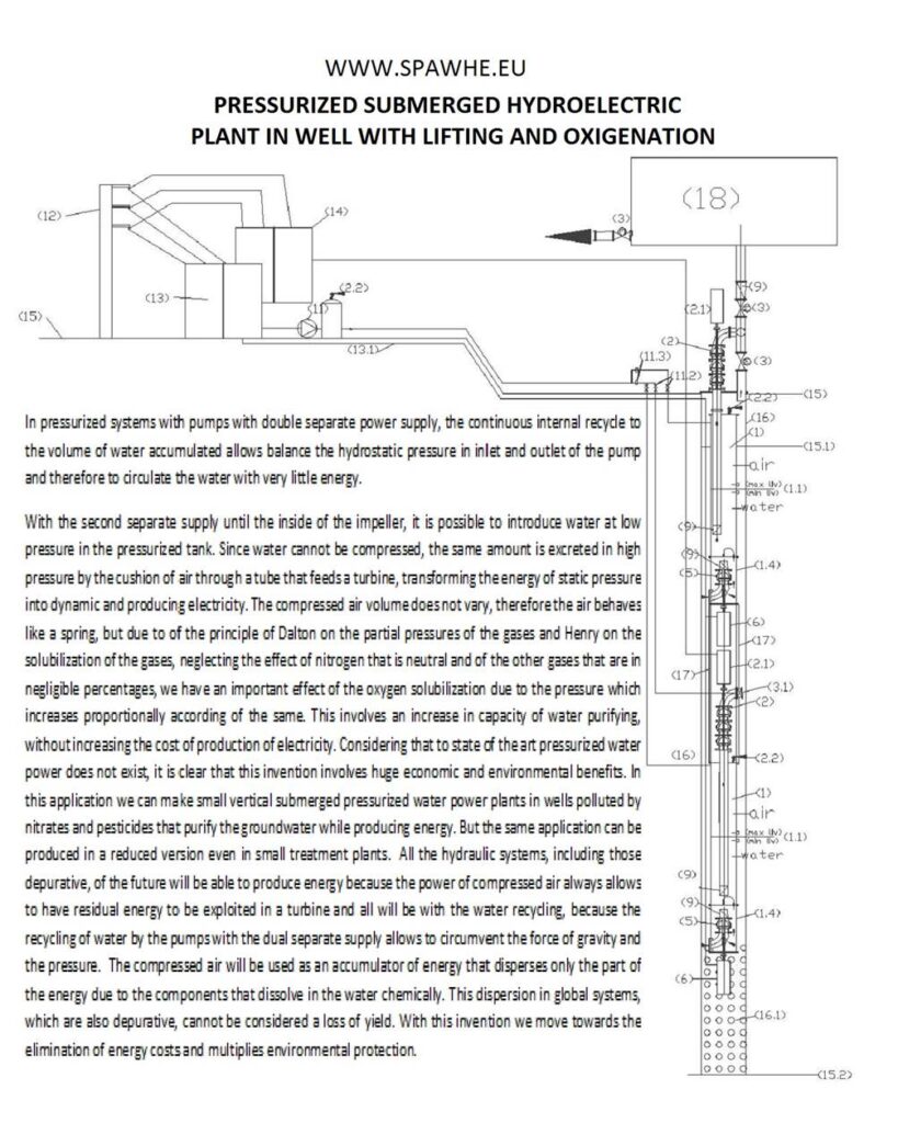
The plants in question are very convenient energy and biological point of view by applying very simple physical principles such as that of communicating vessels. Thanks to this principle of internal and external pressures are equal to the immersed tubes. This not only allows you to withstand huge pressures but also allows you to use one-way energy shallow water position by means of the pump creating intubate currents with very low energy consumption. In fact, by calculating the position in which we install the pump, under the head, we can do so that the curve of the resistant conduct and the pump curve that insert for the circulation would meet on the zero line of the geodetic head and where also the kinetic energy and pressure on suction and discharge are reset each being P1 = P2 and V1 = V2 (due to the swing on the pump specially calculated) according to the relationship H = 0 = (P2 – P1) / γ + (V22 – (V12) / 2g. In fact, in the open hydraulic circuit realized, the water with the pump stopped it is to inertial state and for the principle of communicating vessels fills the entire circuit. To circulate the calculated flow rate should be a pump with a prevalence that depends on the hydrostatic head at the inlet thereof, as in all open hydraulic circuits. If the load losses are calculated with precision, as soon as the pump begins to turn, finds its point of operation with a few centimeters of prevalence, and a deviation from the nominal flow rate, which depend on the accuracy of the calculation. This case does not exist in plants realizable at atmospheric pressure, allows us to move many m3 / s of water per kilometer vertical paths consuming very little energy and also reduced installation costs, considering excavations, landfills, road crossings, expropriation, necessary in terrestrial applications.
Another basic principle on which these systems are based is the theory which is based on the Bernoulli notes Venturi pumps that allow you to suck from the abyssal depths, without the mechanical part of the water or sludge present in the seabed. In fact, the Bernoulli law states that: “If the fluid flowing in a conduit provided with a constriction in which V1 and V2 are the speeds, S1 and S2 are the respective surfaces of the sections, the manometric pressures P1 and P2 measured at those sections, to the principle of conservation of energy is established the following relationship: P1 + ½ d V12 = P2 + ½ d V22. The constancy of the value of the expression shows that, the greater and ‘the speed difference in the respective sections and the smaller the pressure difference, and vice versa.
Unfortunately, the average depth of the ocean waters, corresponding to the abyssal plains, ranges between 3000 and 6000 m, but on the other hand are characterized by the absence of waves on the surface. This allows us to design systems fully floating.
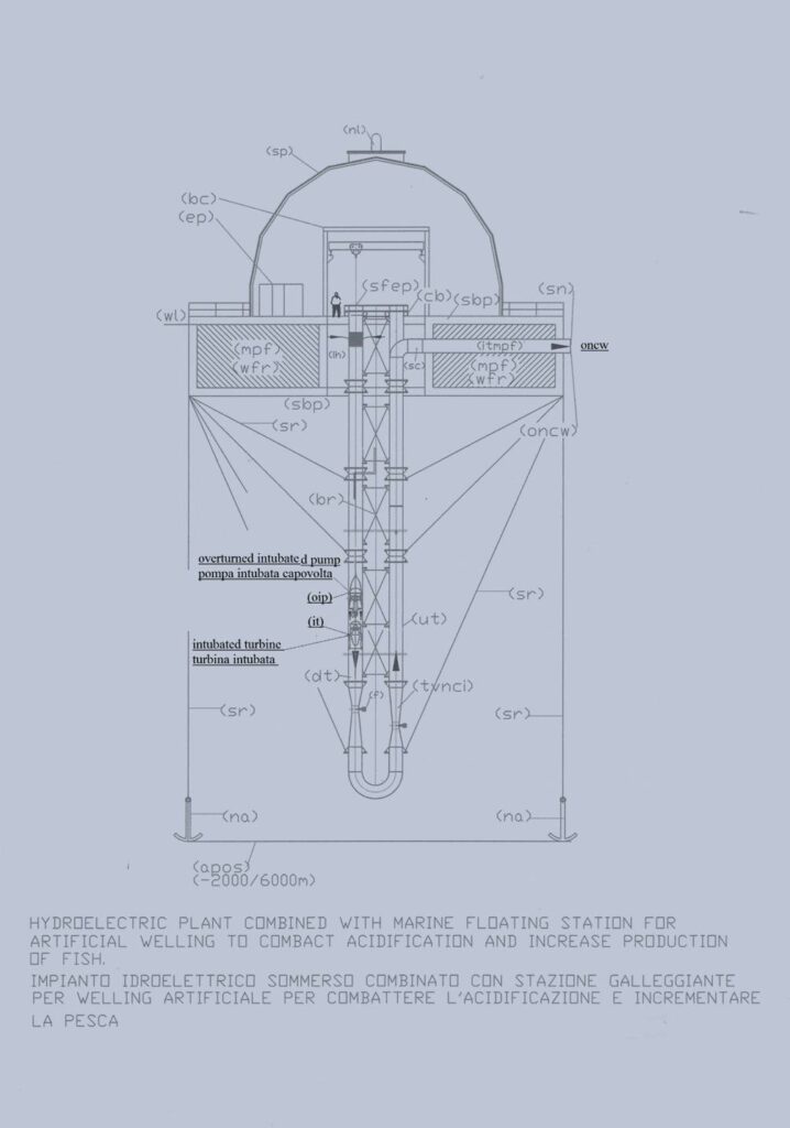
Assuming you make a “upwelling” system on a backdrop set at a depth of 6 km, and then, with a total of 12 km of downhill tubing (dt) and rise (ut), Dn 1400, which also contains the electric pump in the stretch (dt ), with a flow rate of 4,000 L / sec, V = 2.6 m / sec, the pressure loss in m / km calculated with the formula of Bazin (1.000 * 4 * V2 / C2 * D) where (C = 87 / (1 + 2g / √D) and a roughness coefficient g = 16, are 4,11 m / km, for a total of 49.32 m. The pressure drops localized in 2 venturi bottlenecks with D2 = 700 mm (V2 = 10.4 m / s) is equal to 5.51 m (2 * 0.5 * V2 2 / 2g); the load losses in the curve at 180 degree radius 1524 mm is equivalent to 0.34 m (2 * 0.5 * V1 2 / 2g), the load losses in the element of the final water outlet estimated at 0, 34 m. Therefore, the head necessary for the circulation of 4000 l / sec in this circuit is about 55.5 m. By installing the electric pump at a depth of 54 m from the surface whereas the density of sea water is 1.025 t / m3, we choose an electric pump, which to give the required flow works with a prevalence of only 0.2 m, since no pump can work at a zero head. It will be the effective hydraulic resistance of the circuit to establish the precise point of operation of the pump but always within a few cm of difference regarding the prevalence. Considering a total return of 70% of the electric pump, the power consumption would be (N = Q * H * 1025 * 102 * 0.7) = 11.5 Kw. If under the pump we install a hydraulic turbine that works with the flow rate of 4000 L / s and a loss of load of fifteen m, we must not increase the power of the pump motor, it is sufficient to install the pump and the turbine to a depth of 70, 5 m instead of 55.5 m darkened due to the load losses of the circuit. If the turbine efficiency with its alternator is 0.8, the energy produced will be 482.34 Kw / h (4,000 * 1,025 * 15 * 0.8 / 102).
The figure below shows the composition of the system, which will also use solar panels, to heat water and other industrial uses. In fact, these systems allow the colonization of oceanic flat for the purpose of food production and tourism means of artificial islands. In the future, thanks to this invention, will be much cheaper to eat fish than meat.
Legend = Legenda (apos) abyssal plain ocean seabed = fondale piana abissale oceanica; (bc) bridge crane = gru a ponte; (bcb) bracket cross bracing = staffa per controventatura; (br) bracing = controventatura; (cb) clamp brackets = staffe a morsetto; astal seabe fondale costiero; (dt) descent tube = tubo di discesa;(ep) electrical panels = quadri elettrici; (fsp) flange for support pipe = flange per supporto tubazioni; (ih) immersion hole = foro d’immersione; (it) intubated turbine = turbina intubata; (mfp) modular floating made of polyethylene = galleggianti modulari in polietilene; (na) navy anchor = ancora marina; (nl) night light = luce notturna; (oip) overturned intubated pump = elettropompa intubata capovolta; (oncw) output nutrients and carbonates rich water = uscita acqua ricca di nutrienti e carbonati; (sbp) supporting base platform = piattaforma di base portante; (sc) socket connection = tronchetto di collegamento; (sfep) special flanged end pieces = pezzi speciali flangiati di accoppiamento terminale; (sp) solar panels = pannelli solari; (tvnci) throttling venturi nutrients and carbonate intake = stozzatura venturi per aspirazione nutrienti e carbonati; (ut) uphill tube = tubo di salita; (wfr) waterproof floating room = camere stagne galleggianti; (wl) water level = livello acqua.
5) CHANGING THE PUMPS
In other terrestrial applications, if we really want to avoid immense energy waste, and we want to reduce large works such as dams and water reservoirs in the mountains we need to change the entire system of raising and management of drinking water, for industry, agriculture and also for the defense of the territory against flooding. In fact, we can do all of these works producing energy instead of consuming it.
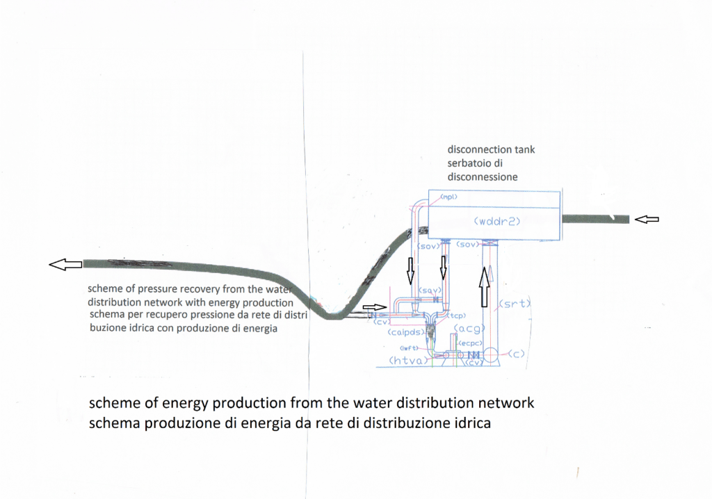
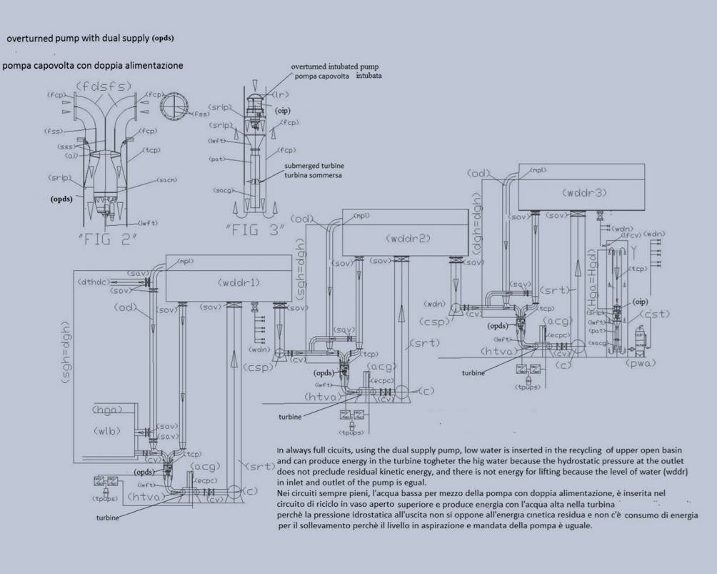
It is necessary to change the pumps, not design, because the technology developed in this area is huge, even more than than it actually need. In this sector lacking only the pumps with dual power supply on the suction side, that will allow to feed the impeller with two flow having different hydrostatic pressures and thus use may be to use the greater hydrostatic pressure to lift water with hydrostatic pressure lesser, non-bypassing the force of gravity and atmospheric pressone but using them in one direction. In fact in the phase of descent of the water the natural forces help the pump to drive the turbine which converts the kinetic energy into electrical energy, while at the turbine outlet, the water would rise upward carried by the water recycled in the open vessel and the pressure recovery permitted by enlargement of the section of the connecting pipe to the tank top. Therefore, as in submerged hydroelectric, they will exploit the force of gravity and atmospheric pressure in the phase of descent of the water. But not being able to have large volumes of water, to produce energy submerged, the water is raised, at low cost, by inserting it in the recycle loop connected to the upper reservoir.
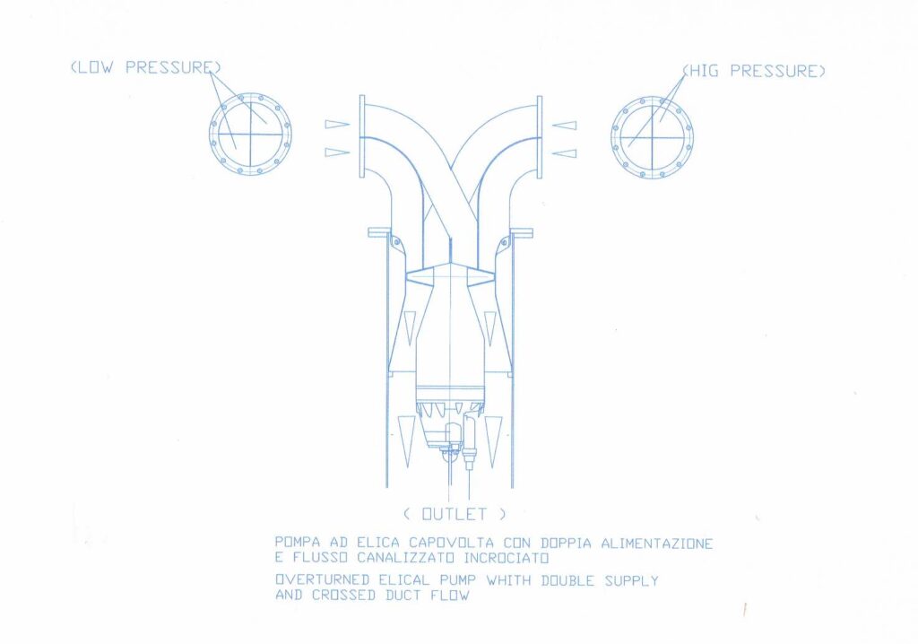
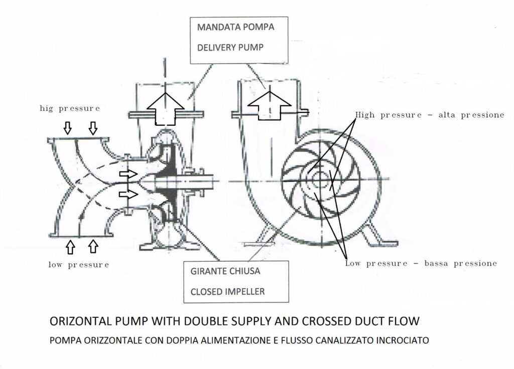
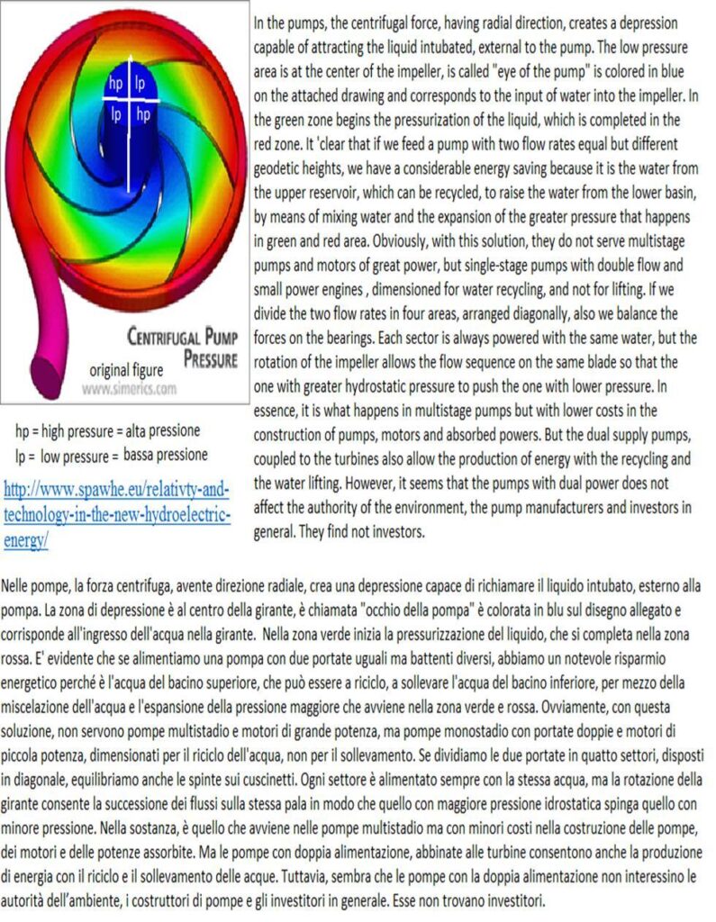
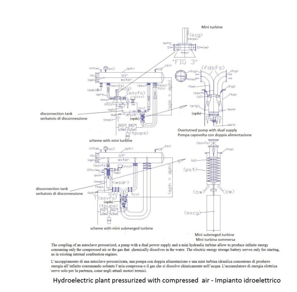
The pumps dual power supply on the suction side, do not exist but are simple to realize by changing the pump power supply current, not the construction technology of the same. In fact, by feeding the impeller from the outside by two confluences (curved or grafts with different angle) channeled internally, so that the two flows cross each other and nourish the pump impeller into four separate sectors, arranged diagonally, two fed with water to be lifted and two fed with recycled water from the top, equipped with high hydrostatic pressure. . Balancing in that way, the hydraulic thrust on the impeller and bearings, and by getting its flows right into the impeller, so that there is no contact before being dragged from the impeller, we can turn all plumbing current by absorbing energy to producers of the same, of course, also modifying the installations.
We start from the heart of a pump that is the impeller, which can produce an axial flow, semi axial or radial and can be opened, closed or semi-closed, depending on the pump body in which is mounted. There are also pumps with impellers double, with horizontal shafts and dual fuel at the same pressure, that have excellent performance, but we do not take them into account, since the pumps that we propose to take advantage of both the hydraulic principles of communicating vessels and Pascal, who allow increments of flows and pressures at low energy cost, they must be supplied with different hydrostatic pressures
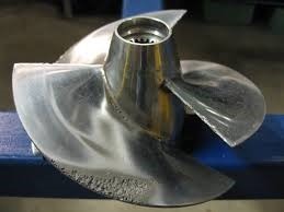
The helical impeller is constituted by a propeller that lets water through and produces a conical flow, giving a low increase in pressure and acceleration.
GIRANTE APERTA – OPEN IMPELLER
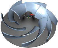
the open impeller is constituted by a disc on which are arranged the vanes which guide the fluid towards the periphery of the disc conferring an average increase of pressure and acceleration.
GIRANTI CHIUSE – CLOSED IMPELLER
the closed impeller as the impeller is open but is equipped with an against disk which has the function of stiffening the vanes to fortify them, both to reduce leakage, being used to transmit higher pressures.
There are many other types of pump impellers for dirty liquids and cleaned, tested, and proven for each application. These impellers are a cross between these three main types.
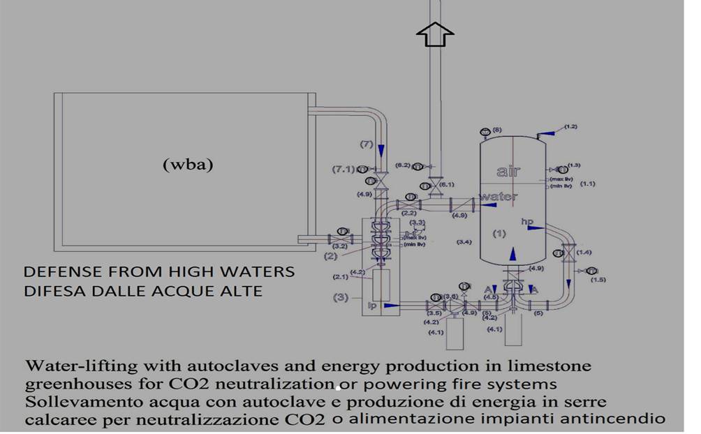
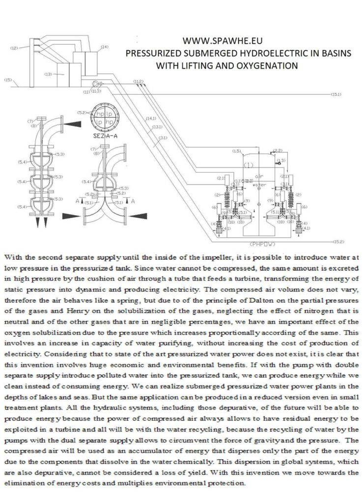
The below figure shows an electric pump ducted turned over to make better use of the hydrostatic pressure of water with axial or semi axial flow for high flow and low heads, to power a hydraulic turbine and produce hydroelectric power also raising a part of the water circulating within the pump. The system can only operate if the mouths are fed under the head and equipped with check valves, in particular for the mouth fed with less pressure. As you can see from the figure, the two power supplies are divided into four sectors, but only two per side, arranged diagonally, are fed. In this way, the impeller, enter four streams with hydraulic forces balanced. It will have to be the rotation of the impeller to mix the flow rates so that the output of the pump has only a single stream. The pressure drop that you will have in the pump due to the entry of water with a lower pressure, can be recovered with the widening section pressure line, dynamically applying the principle of Pascal. Which states that the pressure in a closed tank expands in all directions, but in this case, given the rotation of the pump and the presence of the check valves on inlet, it will expand only in the direction of the flow, also thanks to the reduction of the water velocity in the output section (Bernoulli’s theorem)
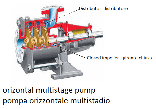
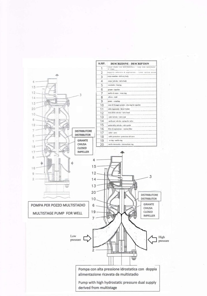
Today, to lift water at high reservoir win high load losses of long distances using the multi-stage pumps with closed impellers. In the multistage pumps the pressure increases by means of distributors which connect the impellers in series. The distributors are formed in the body of the pump, assembled and connected in series with bolts or tie rods, by interposing the sealing gaskets between one stage and another. They consist of various channels that bring water to the center of the impeller next so that the same flow rate gradually undergoes an increase in pressure and acceleration. Basically, it can be said that the dual fuel channeled to the pump, which feeds the impeller mono stage exploiting the hydrostatic pressure external to the pump, acts as a single distributor of the flow of pressurized water, eliminating other distributors and impellers.
It ‘obvious that using the technology and the fusions of a multistage pump, by modifying the first stage and making double-fed, and then, by coupling only with the last stage, we can provide a pump with low prevalence, but with a pump body suitable for withstand high hydrostatic pressures, which coupled to a motor of low power, allows recovery of the level of the upper basin (or pressurized), by the insertion of water with low pressure in the recycling circuit, entering into the impeller from the suction side, with a separate stream. If the passage sections are adequate, the water that enters in the circuit is raised to the upper level by the same hydrostatic pressure existing in the recycling circuit, and the effect of the communicating vessel necessary to the condition of recycling, both due to the principle of Pascal, which as said above, it intervenes downstream of the impeller. Obviously, a pump that uses these two hydraulic principles essential for the conservation of energy, has lower costs than traditional pumps, and systems that utilize exploit to the maximum the principle of conservation of energy. The pumps are designed to be current with hydraulic principles opposed to energy conservation. If the pumps were wrong, were also wrong motors which have been coupled. And the great diffusion of the pumps in all fields of industrial and energy, it can be stated that from the point of view of energy consumption, in addition to the environmental, the first industrial revolution has failed. However, the technologies developed are valid and would allow us to quickly recover the lost time if there were less hypocrisy among those in the public and private works.
In fact, if works a multi-stage pump that for the accuracy of the machining of the rotors and distributors manages to reach pressures of hundred bars, without that the water return back, it must function also the pump with dual power supply which is based on the same principle and even the quality of the machining, while bringing through distributors, starting on the outside of the pump, four separate streams, with two different pressures, which meet, only within the impeller, not a moment before. It is also important to the shaping of the terminal part of the walls of the distributor on the profile of the impeller blades and the adjustment of the water flow entering the impeller, since if the flows will cross before, the turbulence that would be generated, would not allow the operation of the system.
The figure below shows the interior of a multistage pump which increases the water pressure passing from one stage to another.
The figure above shows a horizontal single-stage pump, modified with double inlet, which increases the water pressure to be lifted by means of the recycling and mixing with the water from the upper reservoir. The division of the flows, being separated, allows the alternating supply of the same impeller blades with different flow rates and pressures, for which the greater hydrostatic pressure is also transferred to the waters with lower pressure.
The system is also valid in the underlying pump, derived by modification of a multistage pump for well.
In pumps dual power the rotation of the impeller as well as increased the inlet pressure, mix the two half-flows, therefore, at the outlet of pump will have a single flow and a single pressure (due to the principle of Pascal). In fact, both in a closed circuit, both in a circuit in an open vessel, where the geodetic heights coincide in suction and delivery, the prevalence of the circulation pump not dependent on the hydrostatic pressure of the system but by the load losses due to friction that exist in the circuit, which are dependent on flow rate and the speed of the flow, not by the pressure of the circuit, since water is an incompressible liquid. This physical phenomenon, until now has not been sufficiently used both in the lifting of water, both in hydroelectric energy production, but is also confirmed by the current criterion for calculating the prevalence of the pumps that are used in closed and open tank used, especially, in civil and industrial heating systems. It may sound strange but a heating system at sea level, even if he had the expansion vessel to a thousand meters high: it would not change the prevalence of the circulation pump and the engine output coupled to it, but should change the pump housing, the valves and the thickness of the tubes to withstand such pressure.
5.1) Reflections on the functioning of modified pumps
One person asked me how it might be the characteristic curve of this type of pumps. To answer this question, I decided to put these reflections at the end of the chapter of the pumps change.
The current state of the art of public lifting installations is characterized by the fact in a central are different pumps which add up their flow rates in same conduit, in general, raising to a tank located on a hill that distributes the water to fall. The amount of pumps in operation depends on the consumption of water detected by the lowering of the upper basin level. Therefore the operating point of the pump varies. When the pump works alone absorbs more power because it works with lower prevalence gauge and therefore higher capacity (Power consumption varies with the square of the flow rate and varies with linear proportion in relation to the prevalence). To design a hydraulic lifting system are needed in the following sequence, which express directly with an example:
- To establish the position of the starting and arrival of basins and geodetic height difference between the two basins: 280 m;
- to establish the approximate volume flow: eg. 300 L / s, and the number of pumps: 3.
- to establish the route and length: eg. 2 km and the diameter of the pipeline: eg. dn 500
- draw on a diagram, drawn to scale, the curve Conduct resistant, placing on the abscissa the flow and on the ordinate prevalence, starting from the geodetic difference, after determining the load losses in the pipes and the central lifting valves: eg. 2.5 m. therefore, the conduct of the starting point is 282.5 m. In this case, each 50 L / S and are shown in the vertical load losses above the horizontal line passing through the 282.5 share, to detect the passage of the curve points.
- Mark the meeting point of the curve of the pipeline, at the rate of 300 L / s, and divide the space into three equal parts at maximum total manometric pressure 292.9 m (282.5 +10.40).
- To determine the prevalence of the pump to the previous point by subtracting the positive swing of the suction basin on the pump shaft: 5 m, therefore, the prevalence to be assigned to the pump is 287.9 m (292.9 -5)
- From the point of intersection of the first pump with a maximum head of line plots the first curve of the pump (starting from left), which will meet the curve of the conduct to a point with higher flow rate and head lower than the nominal, calculated above. Therefore, the pump operates with less efficiency at rated point (100 L / s, 287,9m), as shown in the attached diagram. Then he makes the parallel, reporting faithfully horizontal distances of the various points of flow and yield curves in order to establish the system operating conditions with two pumps in operation. In essence, only with three pumps in operation, you can work with maximum efficiency.
Obviously, as mentioned above the pump which absorbs more energy is the one that works by itself and you can calculate the absorption with the usual formulas. The entire plant with three pumps in operation and performance 0.7, absorbs about kw 1209.6 (3 * 100 * 287.9 / 102 * 07).
The figure below shows the graph of the test procedure above.
I reported above the complicated procedure to determine the pump operating point to make things easier and the benefits include energy savings that with dual supply pumps are immense. In fact, the dual supply pumps, can be used to save energy, or even coupled to turbines to produce energy. In both cases it increases the size of the pump casing and the impeller or impellers, doubling the flow rate, but decreases the prevalence of the pump and the power of engines that will be coupled.
The first solution is very simple, as shown in the following figure:
From the discharge line it derives feeding of about 50% of the flow that comes from the pump on the second suction mouth, adjusting the flow rate with a needle valve (sav), so that the water under pressure, mixed with water coming to be lifted from the water basin (wlb), allowing the reduction of the number of impellers and is the same pressure of the water column flow to provide most of the energy for lifting. As can be seen from the diagram, the upper reservoir is at a constant level since the water raised, through one or more overflows, is discharged by gravity to the water distribution. Being a single tube that goes up to the upper reservoir can not speak of recycling, however, we can not avoid noticing that the geodetic height in suction and delivery of the pumps is the same, even if for only one of the suction intakes. In this case the open tank (wddr1) works as an expansion vessel connected to a water recycling circuit in the lower zone. In fact, in large heating plants, with closed or open vessel, the vessel determines the hydrostatic pressure of the circuit, not the prevalence of the circulation pump that is determined by the load losses by friction in the circulation in the pipes and valves.
What is important are the passage sections. For this reason, the pump is sized for twice the flow rate to lift (200 l / s). Therefore, eliminating the geodetic (sgh = dgh), the pump head should be limited to overcome the loss of the circuit with a double flow into the pump, but limited to the field of the lifting plant, as the recycling of ‘ water is only in the context of the plant, without involving the collector that rises to the upper reservoir. This solution allows you to save the existing pipelines by changing only the plants for energy saving. The internal operation of the pump has been widely described previously.
But as you can see from the diagram also above the pipe lifting equipment can become energy producers. In fact, the hydrostatic pressure can be exploited in separate circuits without raising the water to the upper reservoir. Instead of stopping the pumps, as is done in existing power plants, you can be downloaded in the lower tank a flow rate equal to that taken from the same basin, but pressurized by the hydrostatic level of the upper basin. In this case, we insert in the circuit a turbine and a control valve, possibly connected to a flow meter, which discharge a scope identical with a pressure drop in the turbine and in the valve of about 280 m. The energy produced by such recycling, for each turbine, which automatically enters into operation when it is not necessary the water to the upper reservoir, assuming the yield equal to 0.7, is about 192 kW / h (100 * 280 * 07/102). While the energy spent for the entire operation of the plant, suppositories the load losses in the central it is 5 m, it is kw/h 63.4 (3 * 15.4 * 200/102 * 07). This energy is much lower than that consumed today for lifting water to the same share as calculated above (Kw/h 1209.6) without the exploitation of the higher hydrostatic pressure, gravity, and the performance of the dual supply pumps, regardless of 192 kw / h can be produced for each pump and turbine that recycle the water when it is not raised.
As can be seen from the above diagram, wanting to try to put on paper the curves of the dual supply pumps with the criteria used up to now, we are in considerable difficulty, because the pumps perform most of those current functions. In this scheme, we can highlight that the curve of the pump meets the curve resistant of the conduct with the flow portion raised by the pump (100 L / s) while the other 100 L / s are recycled within the same plant. But this curve is conditioned by the fact that the sections of passage in the tubes and in the pump are able to completely reset the geodetic difference in suction and delivery of the pump. In fact, the hydrostatic pressure of the upper basin is transmitted by the connecting pipe (srt) which has a section of passage of 1962.5 cm2, which is divided into three feeds of the dual supply pumps. Each supply opening must have a minimum section of 654 cm2 passage (1962/3) that corresponds to a diameter Dn 250. If you do not meet these conditions, you must increase the pump head. In fact, Pascal’s principle states that the pressure in a closed environment expands in all directions, but to exert a force dynamically is necessary to multiply the unit pressure to the passage section. By resetting the geodetic difference with this system we can put on paper the pump curve, and we can understand that instead of having a prevalence of 287.9 m of water column, will prevail required to overcome the pressure drop in the central and in the conduct of lifting (15.4 m).
But if we want to produce a greater amount of energy it is necessary to realize a circulation of water one way that uses the energy of the water circulations in vertical position, together incompressibility of water need, short and linear circuits, with very few losses of load and supply pipes and return linked to the upper basin. The best solution is to raise the water in steps, with pumps with dual power supply coupled to the turbines and ascent and descent pipes, that by recycling the water, exploit different physical principles: advantageous for the production of energy in the descent and thrifty for the rise of water, which, as said, in the introductory part, in plants always full, it may even be avoided, being equal to the density of water, on the surface and below. Then, the energy for the ascent can be minimized by increasing the sections of the pipes and retaining constant level of the upper reservoir, where the large volume (respect to the recycling flow) feeds the water fall towards the pump and the turbine and surface overflow for raised water.
Therefore, the plant taken as an example that today consumes 1209.6 kW, which could consume 63.4 Kw occasionally producing 192 kw with each turbine, it can become even more advantageous. Does not depend on pump operating curves, but the simplification of systems with dual feed pumps.
In fact, the profile of the conduct may be such as not to allow the realization of the previous solution (single pipe), because of depressions that do not allow the regular circulation of the water and the air vent. In this case, we can divide the plant in 6 plants with a geodetic difference in height of 50 m. Each plant uses only one pump always in operation that recycles the entire flow rate (300 L / s) fed through the valves (sav) both suction intakes from the upper reservoir, or, raising about 50% of the flow, by entering the water, with a positive pressure of about 5 m in the same circuit, from the suction side of the pump, using the second suction mouth. In this second case, which exploits the energy of position of the water of the basin on the upper level, with a return pipe, if the flow sections are adequate with both pipes connected to the upper reservoir and this is connected to the atmosphere, remain the conditions of absence of the geodetic difference between a suction inlet and the delivery of the pump. The suction mouth is located from the downward side of the water that benefits from the weight of the water column that moves in the gravitational direction and the atmospheric pressure, the water outlet is located in the tube of larger cross section which is equally connected to the upper basin, from the side where the atmospheric pressure and gravity play an opposite function, but lacks kinetic energy. Therefore, the only opposition that can have the water circulation is the friction with the molecules of equal density, lack of energy in the larger tube. The kinetic energy developed in the descent is dispersed into heat in the receiver tube, there is no need even lifting water, being the basin at a constant level. If there were the turbine does not slow the speed of the water, producing electricity, the water speed would be much higher, and instead of producing electricity would produce heat. It would be a very stupid thing. If in place of the second tube there were a large reservoir communicating with the upper one, as shown in paragraph 2.1, there would be no water ascent due to the kinetic energy remaining. It would be just a change of surface water location, restored from other surface water, because water takes the form of the reservoir that contains it, with the least expenditure of energy, always chargeable to the friction between the molecules in the submerged outlet. For this reason, we have to go out in a large section, similar to the vertical extension of the upper basin.
Assuming the yield equal to 0.7, the energy produced in this system that uses six pumps and six turbines in parallel that exploit an average height in the hydraulic turbine of 50 m is about 617.6 KW / h (6 * 300 * 50 * 07/102). While the energy spent for the entire operation of the plant, the load losses in the suppositories of 2.5 m is approximately central kw / h 63 (6 * 300 * 2.5 / 102 * 07). But the energy expenditure can be considered as a reduction in the general efficiency of the plant, not the energy consumption of the pumps, which in this case only perform the function of the state of water win inertia which do not circulate spontaneously, without moving means waters on the lower level. The mixing of the two flows with different pressures is necessary in order to give the necessary pressure to the water with less pressure, with the mechanics used in multistage pumps, but with the energy provided by the static pressure of the upper reservoir. What are unable to make it clear to the skeptics is the fact that we should not raise the water coming out of the turbine. At the exit of the turbine circuit that produced the energy is terminated, with the pressure loss at the outlet calculated by the formula V2 / 2g. If the water goes back or not rises to the surface is a problem that only depend on the overall volume and the implant shape, not from the head of the pump that feeds the turbine. And even if it were up to this, in the absence of the geodetic difference in height and with the sections of passage amply dimensioned, a few hundred meters of pipe, is only a few centimeters of water column pressure drop. Just refer to the tables in chapter “6” to realize this truth.
Who asks the representation of the pump curve that Work in this way, am I ask if he ever seen a yield curve of a flow mixer. Although we will give a few meters prevalence and these very special pumps, but easy to do, the main function, which will play will be to sum and mixing two streams at different pressures. More than one person asked me a few more clarification on this aspect. For this reason I add another paragraph in this chapter.
5.2) The reasons for the division of the flow of water in the pump.
If we observe all the figures of the systems that couple a pump with simple or double feeding and a turbine, we have to take note that these pumps from the operation point of view are different, especially, to a main aspect of the current hydraulic lifting pumps:
Those existing, working with a load manometric and a geodetic difference in level unbalanced, having a small positive suction at the intake and a high hydraulic load in delivery especially constituted by the difference in level between the two reservoirs and the length of the lifting conduct.
While in the new hydro solutions pumps are operating with a load manometric and geodetic balanced since at least one suction inlet and the outlet have the upper level in common. Therefore there is no geodetic head. But existing, however, always, a high positive head on the pump suction, and knowing that the hydrostatic head, alone, is not opposed to the kinetic energy, the system would even be unbalanced in the opposite direction to the existing lifting equipment, dispersing in heat immense energies, if we did not use a turbine to balance the hydraulic load, slowing the speed of the water, with its own resistance. In other words, because the water moves in the direction of the gravitational force pump must provide the amount of energy to overcome the inertia state but as regards the flow rate mainly depends on the passage sections in the tubes and in the pump and by height h (which is the location of potential energy). If the sections are not sufficient to obtain the desired flow rates it is necessary to increase the prevalence of the pump, but not to lift the water, which is always discharged in the lower extension of the upper reservoir with a pressure drop V2 / 2g. Obviously, as written above and below, the extension of the upper basin cannot be kilometers long and of small cross section, otherwise it is not comparable to an appendage of the tank where the water uses its own internal energy to take the form of the reservoir that contains it. Even in this case the hydraulic system adapts to the general load losses and the flow coming out from the turbine is reduced but not stopped. It may do all the calculations of the speed, the pressure loss of the machines and returns to approach the capacity of the system, or simply insert a flow meter downstream of the turbine. Based on this measurement, change the pump or the general structure. But what is important is to understand the reasons why the existing lifting equipment must be modified, and especially the pumps: dividing the power in four sectors until the entry into the impeller, if we do not want continue to waste energy for infinite time against gravity to lift the water and continue to not produce the simplest sustainable energy and economic of the world.
The two figures below, it best describes the modification using two drawings extracts from the web, showing the source of the original designs.
6) MODIFICATION OF LIFTING WATER FROM ABSORBERS TO POWER PRODUCERS
The current world water management is against the general principles of conservation of resources, energy, physics and mechanics. It ‘easier to understand the employment waste in one way of the water, which could be recycled. Today, recycling is too expensive from the point of view of energy since they are not built systems that bypass the universal gravitational force. In fact, everyone knows that from an energy standpoint, it is much cheaper to raise a body through an inclined plane, winning the sliding friction resistance that raise it directly. But men to improve this system, from thousands of years have invented the rolling friction, the transmission ratio belt or gears between wheels of different diameters, and today, along inclined planes consumes hundredths of energy than that which would be required for the directed lifting of the masses against the universal gravitational force. In the hydraulic sector the equivalent of the inclined plane is the exploitation of the variations of legislated sections in the formulas of the Bernoulli and Pascal’s principle. But these principles alone are not enough to significantly reduce the costs of hydraulic lifting because in the plumbing industry lacked the invention of something equivalent rolling resistance, which improves overall performance through the transport machinery and mechanical lifting. In the hydraulic sector to the invention which can be considered equivalent rolling resistance, is the invention of the pump with dual power supply on the suction side, which, combined with the Bernoulli principle, Pascal and to the principle of communicating vessels, allows to exploit the gravitational force one way, also lifting the water. Modifying the existing hydraulic lifting systems with the introduction of these pumps, the performance of the water lifting comes very close to the yield of mechanical lifting using the inclined plane and the rolling friction, although based on completely different principles. In fact, the mechanical lifting exploit much longer paths, while the hydraulic lifting movement to a quantity of much higher than that to be raised always filled water circuits, since it is the same water with the geodetic height superior to raise the water of the basin to place lower level. But the system is equally highly advantageous. Just think that recycle an m3/s of water in a thousand meters of pipe Dn 1000 requires the same energy of a 1.5 m lift, as shown in the tables in this chapter. So if we recycle at low speed 1000 L / s, we can lift about 500, with yields similar to those allowed by the mechanical lift on an inclined plane and rolling bearings. But once they were invented pumps, continuing to think about changing the hydraulic systems, you can easily understand that the hydraulic systems will largely exceed mechanic systems. In fact, the mechanical systems while increasing the yields remain consumers of energy, while the hydraulic system contains the material that can be transformed into energy, taking advantage, as mentioned above, the energy of water located in the upper position with respect to the one placed down, without wasting water. Also, if a hydraulic system is coupled to a pneumatic system and mechanical you can create a single even more complete system that contains other matter converts into energy, such as compressed air. In fact, also the compressed air has an energy of position relative to the not compressed air. The skill of the mechanical and pneumatic hydraulic diagram designer is to make the most of the principles and technologies that do not waste energy, transferring from one system to another. Obviously, consuming a small part of the energy produced by the recycling of water, including that which passes in a turbine and is replaced in the recycling loop by a suction mouth of the pump with double power. Another small energy consumption requires the restoration of the compressed air cushion which requires solubilization of the gases in the water. But they are small compared to the energy consumption transformed without the use of fuels. The system with compressed air is described in detail in chapter 9.
Considering that current technology allows you to build multi-stage pumps with pressures up to 100 bar (1000 m), as described above, we can use the pump bodies of the current multi-stage pumps (to withstand hydrostatic pressure) but otherwise connect them using only the first and the last stage, saving in both the absorbed power for lifts, both in the construction of pumps, both in the construction of the motors.
To understand the extent of energy savings is attached below a table showing the pressure drop of the pipes calculated with the formula Bazin- Fantoli: (1000 * 4 * V2 / C2 * D) where (C = 87 / (1 + 2g / √D). from this table we can detect the loss of load of a thousand meters of pipes with different flow rates and different coefficients of roughness (range). the coefficient range most used in hydraulic calculations is “16”. They are reported only two diameters to set the reasoning Dn 100 and Dn 1000. If we analyze a flow velocity of about 1.5 m / s for both dimensions, we may note that since the power is absorbed by a pump equal to Q * h, we can consider the load losses reported in the table, as the prevalence “h “required in a pump to lift the same amount of water. The energy ratio between the recycled water (which requires no lifting) and the water raised to the atmospheric pressure, in the two cases examined is the following:
in the case of pipe Dn 100 (with a flow rate of 11.8 l / s) is equal to 48.3 / 1048.3 = 0.0460 = 4.6% of the power needed to lift;
in the case of the tube Dn 1000 (with a flow rate of 1180 l / s) it is equal to 2.079 / 1002.079 = 0.002074 to 0.02074% of the power required for lifting.
The remarkable difference between the two ratios, for the same flow velocity, is due to the greater contact between the flow and the walls of the tubes that exists in the pipes of smaller dimensions. But even in such cases, it is less advantageous, irrespective of the technical advantages (which will enable new hydraulic circuits that will lead to energy production in hydroelectric installations fixed and mobile, exploiting different hydraulic schemes, as described widely in its stores patent), the economic advantages to choose these types of pumps and systems for just lifting are immense. In fact, in the table below, we can see that if we double the water flow rate, to maintain about the same speed in the pipe, the pipe size DN 100 must be brought to DN 150:
In this case, the pipe Dn 150 (with a flow rate of 24 l / s) will have the ratio of the recycled water and the water raised to the atmospheric pressure equal to 21, 68 / 1021.68 = 0.02122 = 2 , 12% of the power required for lifting.
Thus, we can note that, by increasing the size of the pipes, whilst retaining the same speed in the pipes, the pressure drop and therefore the power absorbed by the pumps diminishing exponentially. The advantage becomes even more noticeable with large capacities and large pipes, where the load losses affecting even less. In fact, in the case of the pipe DN1000, we spend the same energy to lift 1,180 L / s of water height of 2, 079 m, or to recycle it in a kilometer of pipe.
This simple reflection brought myself to change lifting equipment and water pumps, not to counter the law of conservation of energy, but to accommodate it. In fact, you must first design the plants, favoring the atmospheric pressure and gravity, then we design machines that are used to establishing installations. The first that must be changed are the existing pumps, which are hydraulic machinery operators who, receiving mechanical power from an electric motor or internal combustion, the transmit, to the liquid which passes through them to increase the pressure. This pressure, in most cases, is used just to overcome the force of gravity and atmospheric pressure. The figure shown below shows a classic system of lifting water without recycling of water.
| Vertical electropumps Elettropompe verticali |
Designers who design the pumps, the professors who design public-lifting equipment, to large multinational companies specialized in large contracts, have escaped some laws of physics and hydraulics, as the principle of communicating vessels and that of Pascal, which would allow to raise the water taking advantage of the greater hydrostatic pressure of the basin of arrival. The system diagram above refers to one of the plants of water lifting the largest in Europe, that I attended to realize as a simple technical employee, in 2000 -2002. It includes a great work of taking water from the river Flumendosa (in Sardinia) and a plant for lift water with five vertical pumps 1000 L / s and 220 m head connected to engine power of 3150 kW, powered 6000 v.
This facility, designed by an autonomous body of Flumendosa with the Company Termoeccanica pumps, motors Ansaldo, made by the company Impregilo, with the electromechanical works subcontracted to the company “Ing. Caccavale and C. sas “of which I was an employee, is a flagship of the Italian technology, and yet, according to the signed, it should be redesigned, according to the diagrams and hydraulic pumps that I propose. Because if it is true that it has the capacity to lift 18.000 m3 / h of water at the height of 200m, also has the ability to consume about 15.000 kw / h, while with the hydraulic schemes that I proposed later, realizing the lifting with four plants step by coupling to dual inlet suppy pumps, and turbines we could produce about. 4.000 kw / h by consuming only forty for water recycling. Beyond all, the plant mentioned has involved complex of variable motion perturbations calculations, made by the University of Naples and for the neutralization of this phenomenon were needed eight steel tanks that are pressurized with compressed air of 70 m3 capacity, with pressure testing of 30 bars. Also the cost of this system could be avoided realizing the lifting with steps in water recycling and dual supply pumps on the suction side, as described, in addition to the present, also in the Chapters 5 and 8.
Mine is not a criticism of the project carried out and the Italian technology, so much so that as the installer, I proudly participated in the realization of this work. But knowing that in the world there are many thousands of lifting water of all kinds, I think it’s been helpful to reflect calmly on these works as pensioner. Because public authorities, large contracting firms, universities, consider acquired state of the art of pumping stations and not seek alternative solutions, however, creativity combined with the experience of those who have seen the implementation of many plants, including by playing small roles , it can lead to the development of alternative solutions, which cannot be shot down without any discussion. The problem is how to convince the large public authorities, large companies, universities, who may have the wrong solutions without hurting their professional pride. The problem is not local but global. I think the stakes are so high that personal pride should be cast aside. Anyone can make mistakes, especially, myself, that cannot compare to anyone and cannot spend a few thousand euro in experiments, but it’s worth to try these solutions. The reputation of a pensioner is worth very little. Risk more powerful that undervalue these solutions.
I do not think to violate the principles of conservation of energy using the hydraulic principles that are confirmed authoritatively in communicating vessels, in Pascal, Newton, Einstein. I think valorize them in contrast to the current technology, which uses the energy produced with fuels to overcome the force of gravity and atmospheric pressure. The undersigned uses these physical resources, existing in nature in the inertial state, by using machines and systems specifically designed so that the lifting of the water occurs with the least possible energy expenditure. But at the same time applying Bernoulli’s theorem, which allows the use of positive head on the pump, I could not realize that, not only we can save energy, but also produce it by changing the pumps.
The hydrostatic pressure in a circuit full of water in the open tank, while not influencing the prevalence necessary to the circulation of the pump, determines the internal pressure and can be measured in meters, being the distance between the upper level of the water relative to the axis the circulation pump. In the above scheme, if we assume the level of the upper basin place to twenty meters of height, and the lower one to two meters, we have a feed pressure of 2 kg/cm2 on a mouth and 0.2 kg/cm2 on the other mouth. The rotation of the impeller, common to the two flows allows, in addition to pressure increase, due to the characteristics of the pump and of the circuit, supposed of 0.5 kg / cm2, even mixing and the sum of the two flow. Into the delivery pipe that leaves the pump, due to the principle of Pascal, the unit pressure in Kg/cm2, spreads in the entire section of the tube, so that, if we entered from the suction side with two sections equivalent DN 100 (78,5 + 78.5 = 157 cm2) and leave with only one section DN 150 (176 cm2), the total force of lifting water becomes 440 kg (176 cm2 * 2.5 kg / cm2), while the input to pump was 172 kg, 7 kg (78.5 *2 + 78.5 * 0.2 ). It ‘clear that the total force of 440 kg at the pump outlet, which is greater than the force input, is due to the pressure recovery (or expansion) caused by the enlargement of the section of the supply pipe from DN 100 to 150. This force is sufficient to recycle the two courses (11.8 + 11.8 = 23.6 l / s) and to overcome the load losses of the circuit, while considering that half of the water is not recycled but raised, not by the pump but from the pressure recovery due to the increase of the section, according to the principle of Pascal. In fact, only one-fifth of the force F is provided by the pump motor.
This system can be used both to protect against floods (pumping stations), both to raise and distribute drinking water or irrigation, both to lift water from wells (using pumps and turbines submerged). In all cases producing energy instead of consuming it. Only the inexperienced who cannot read hydraulic diagrams can accuse me of violating the principles of conservation of energy. The real problem is that no one ever thought to realize these plans, since it was necessary to make proper inventions, such as the combination of the pumps with the turbines, which has never been done, and the change of the pump, creating the double feed.
However are not sufficient only the hydraulic principles, must enter into the pump body and the impeller in such a way that the two inlet pressures do not meet before they are in contact with the impeller. Because, if this were to happen, the water with higher pressure would hamper to the water with lower pressure to entry into the pump. Therefore the two streams of water, not only must be separated, but also guided and shaped on the rotating blades of the impeller. But the advantages that you will have with the birth of dual supply pumps are immense because allowing water recycling allows saving water, hydroelectric energy production without consuming the water and you will finally have an alternative sustainable of thermal energy Mobile, as explained below. For this reason, the dual supply pump on the suction side is the simplest but also the most powerful inventions of our time. The following diagram shows how could be conceived of a water tower or disconnection tank to recycle the water waiting for the producing energy consumption, using gravity during the descent of the water and going around it in the ascent, by means of the pump with double suction power and recycling in an open vessel.
The easiest observation that can be done to the diagrams above and hydropower submerged on chapter “3”, is as follows: It does not happen the pressure drop through the turbine. For the undersigned occur all the transformations necessary for production of energy, since the water that circulates in the descent tube, being subject to the gravitational force and the hydrostatic pressure transforms the energy of position of surface water into kinetic energy during the descent, the passing through the pump and the turbine. The gauge pressure that is measured at the exit of the turbine belongs to the static external waters, which, as written above, may not oppose the residual kinetic energy, apart from the pressure loss at the submerged outlet (V2 / 2g). If this were not true, underwater pipelines may not discharge water into the seabed. Another hydraulic resistance is due to the friction with the walls of the tube in which they download, which can be obtained from tables similar to the one below. But this problem can be overcome by increasing the geodesic height of water on the pump and turbine. In fact, in an open circuit, at atmospheric pressure, the positive geodetic head on the axis of the pump replaces the head of the pump, but at the same time, for the principle of communicating vessels, in the case treated, coinciding the levels of suction and delivery on the pump , water should not be raised. However, if we have a pressure loss in the check valve of 0.5 m at the outlet of 0.2 m, the water ascent involves a pressure drop of 0.5 m, and also if we insert a turbine to produce energy that results in a pressure drop of 10 meters of water column, we can leave the pump in the low prevalence and increase the geodetic heigt of basin (wddr) of 11,2m (wddr) (or, 5 + 0,2 + 0, 5 + 10). If this solution after experimenting equally unconvincing you can move on the presentation adopted on chapter “9” , which is designed for the pressurized mobile version but can also be used for the fixed version. Obviously, this solution is less advantageous, however, best of existing water distribution plants that do not allow the water recycling and not even the production of energy, but they are big consumers of energy.
As can be seen from the above drawing, the output of the turbine flows into the tube (srt) of large cross section, where the load losses for the ascent of the water of a few meters are irrelevant, therefore, the tube can be considered as an extension of the reservoir (wddr) and it is correct to consider the pressure drop at the outlet V2 / 2g. This shows that the hydraulic counter pressure in the case of water circulation in the water does not exist. It would have significant value if in the turbine not circulate water but a solid body lighter than water. In the present case, to oppose the water outlet of the turbine should be another intubation and a pump, which operate with an opposite flow.
Considering incontestable these physical and hydraulic principles, although without prototypes, not made for the lack of economic means, I can assert, unless other laws of conservation of energy that I do not know, in the future we will not need the great hydraulic works, with flooding of mountain valleys and construction of dams, which often produce flood disasters. But continue looking the figure above, we can also say that we can defend ourselves against flooding producing hydropower. The following scheme shows this solution.
This, certainly sorry to the Italian ruling class that is completing the Mose in Venice with the reasonable price of about 5.5 billion euro, according to the latest estimates published in the newspaper “Il Sole 24 Ore”. Instead of creating a work Pharaonic like Moses they could take lower only waters of the urban channels urban artificial water flows, one-way, which flow into the sea by means of hydraulic lifting due to the simple hydroelectric plants operated throughout the year, after reduction of the passage section of the channel, by means of small gates submerged, that leave only the height necessary to the passage of boats. In fact, if we consider the channel to be protected as the basin (wlb) and raise the water to the tank overflow (wddr), the water that comes out of the overflow tube (dthdc) is discharged into the sea while producing energy with the turbine (ht). This plant not only produce energy, but also ensure a continuous supply to the stagnant waters of the urban zone, reminiscent enough water sewer. Obviously, can be done precise calculations flow rates the direction of flow within the channels, in function of passage ports and the size of pumps and turbines, it being understood that in the event of exceptionally high waters the passage opening of the channels could be, further reduced with submerged gate. It is no exaggeration say that a fifth of the costs incurred for the Mose would be solved in addition of high waters problem, also the issue of the renewal of the water, equally important, simultaneously producing clean energy, which should not be unwelcome.
The same scheme can be used for lifting groundwater producing hydroelectric energy.
This, certainly sorry to the Italian ruling class that is completing the Mose in Venice with the reasonable price of about 5.5 billion euro, according to the latest estimates published in the newspaper “Il Sole 24 Ore”. Instead of creating a work Pharaonic like Moses they could take lower only waters of the urban channels urban artificial water flows, one-way, which flow into the sea by means of hydraulic lifting due to the simple hydroelectric plants operated throughout the year, after reduction of the passage section of the channel, by means of small gates submerged, that leave only the height necessary to the passage of boats. In fact, if we consider the channel to be protected as the basin (wlb) and raise the water to the tank overflow (wddr), the water that comes out of the overflow tube (dthdc) is discharged into the sea while producing energy with the turbine (ht). This plant not only produce energy, but also ensure a continuous supply to the stagnant waters of the urban zone, reminiscent enough water sewer. Obviously, can be done precise calculations flow rates the direction of flow within the channels, in function of passage ports and the size of pumps and turbines, it being understood that in the event of exceptionally high waters the passage opening of the channels could be, further reduced with submerged gate. It is no exaggeration say that a fifth of the costs incurred for the Mose would be solved in addition of high waters problem, also the issue of the renewal of the water, equally important, simultaneously producing clean energy, which should not be unwelcome.
The same scheme can be used for lifting water in the follow chapter for the air depuration in vertical covered mechanized limestone green house (vcmlg) and for water depuration in biological superimposed vertical ponds (bcsvp).
7) THE CITY SELF-PURIFYING BY NEUTRALIZING CO2, GLOBAL URBAN DEPURATION AND CONDITIONING
The state of the art of urban air purification is at year zero, while that of water, place to tens of several tens of kilometers from the city, after tortuous sewer pathways that produce ammonia nitrogen and hydrogen sulfide, they absorb a lot of energy and produce acidic waters. The Italian and international environmental authorities have made void the national and international patents SPAWHE, which show that urban air purification can only succeed if we purify water and air together in the same city by means of small and large limestone greenhouses, that break down Co2 and purify and alkalize water. This solution becomes even more realistic and efficient, if most of the electricity is produced by hydropower with water recycling, always invented by SPAWHE, because we will not need of the electricity transport and hence the sewage treatment system will occupy more space in the underground to house the vertical pits purifying water, connected to the limestone greenhouses above and below to the transport of anaerobic sludge extracted at the source to produce biological energy. Therefore, the current treatment system and energy inefficient on all fronts, could become air purifying water, manufacturer of alkaline waters, manufacturer of biological and hydro energy interactive with plant management. In other words, public management systems and sewage treatment would not be a social cost but manufacturers of economic, environmental and human health. Moreover, this way of producing energy, a lot cheaper than coal, not involving the transport of energy, it also eliminates the costs involved, the danger of blackouts and accidental deaths from the high voltages required.
In particular, by the use of dual supply pumps on the suction side, not paying energy, the cost of hydraulic lifting, it will be much cheaper and good for the environment to accumulate water in the valleys than in the mountains, especially where there are thermal plants that produce CO2.Which may be neutralized by means of the artificial rain waters raised with low power consumption, moreover, it produced in the same plant which raises the waters. In fact it pumps allow to achieve at the same time two hydraulic circuits that work with different hydraulic regimes: The sewer overflow discharged from the tank (wddr) can create artificial rain and react with calcareous material specially stored, producing carbonates in the water that would go to counteract acidification of water and soil, therefore, global warming of the planet.
This application, that consume the CO2 produced with fossil fuels producing even clean energy with turbine (htva), can be seen in the hydraulic diagram shown below.
Another lifting and energy production scheme can be realized by exploiting the compressed air to lift the water, without the return pipe from the upper reservoir. But producing energy with the recycling of water to be lifted and that it passes through a turbine, as in the diagram and legend hereinafter reported.
As you can see in the figure below greenhouses limestone may be accompanied by biological superimposed vertical ponds (bcsvp), which would replace the existing activated sludge treatment plants without energy consumption, relying on photosynthesis. The water is depurated simply gradually climbing upwards, consuming the nutrients undesirable, which would produce biological sludge, which would be raised, thickened and digested in a near digester. The biological superimposed ponds can also be used to desalinate large quantities of water, making a circular internally perforated baskets containing ion exchange resins.
The above figure, however, shows an urban scheme that does not miss anything, because, even heating systems and air-conditioning are connected by means of filtration of the air, and the heat exchange with low enthalpy, while the water is purified first into the sewer system, then in the biological superimposed ponds superimposed vertical ponds. Instead, the urban sludge are transferred to the anaerobic digesters. Therefore, the entire system, purifies, water air, exchanges heat both summer and winter with the subsoil, and ends with the production of biological energy. Obviously, in this system will assume a fundamental importance pumps with dual power will eliminate the costs of the hydraulic lifting. The details of this system can be found on the website https://www.spawhe.eu. The figure below shows the detail of the local air and water purification and escape routes of heavy gases such as CO2 and dust, thick and thin.
With the figures above, I interrupted the logical thread of the new hydropower to emphasize that environmental problems are not due only to the energy, but also the inability to design systems globally. In fact, the current global warming, would have never happened, despite the use of fossil energy, if those who pose as statesmen had at least been able to recognize the projects and designers. In fact, my projects on purification global nobody has taken them into account, anywhere in the world. The whole world is country and around the world is the dress that makes the Monaco, not the substance. In fact, statesmen to solve environmental problems are turning to scientists and researchers, which is obviously not know how to design, globally. They carry only their single-issue solutions and do not realize that they are incomplete. To be a designer of global facilities are necessary experiences of industrial plant engineering, environmental, energy, adequate scientific culture and a good knowledge of the organization of work, because first you have to establish the work cycles and the organization’s strategic place in which installing the system. The place cannot be casual, must have the necessary infrastructure and natural resources. Instead, the current facilities are placed randomly on the territory, they are disconnected from each other and even, far away from pollution. Who designed these systems continue to make trouble and to be revered and respected.
Even the existing hydroelectric and water lifting systems are incomplete and trivial technically. They waste immense resources. However, my solutions are making a path even more hidden and quietly opposed by world leaders of the environment and energy.
8) HYDROELECTRIC PLANT WITH LIFTING, RECYCLING AND WATER DISTRIBUTION
Naturally, the most important use of dual supply pumps is combined with the turbines to raise and distribute drinking water and irrigation, energy balances with positive, not negative as those of lifting water current. In fact, the hydraulic lifting, after the means of transport, are today the largest energy expenditure of the planet. Are shown below the schemes of future water lifting systems that are also energy producers. The two feeding mouths of the pump (opds) can be powered by both basins (wddr) placed high to produce energy without lifting water.
Assuming that the overall performance of the turbine and current generator coupled to both 0.8. By suitably selecting the sections of the tubes can bring us back under the operating conditions of the hydroelectric plant submerged shown on 10 -11. In fact, The useful power can be supplied by a turbine which uses entirely the payload Hu than 50 m, intubated with a pump which has a flow rate 1 m3 / s, will Pu = η * 1000 * Q * Hu / 102 = 0.8 * 1000 * 1 * 50/102 = 392 kW; while for rotating the pump in the conditions of balance between the positive head and the turbine just a predominance of a few cm of water column. Supposing work with an electric pump that has the same flow, prevalence 0.2 and 0.7 performance, the power consumption is 2.8 kW (0.2 * 1000/102 * 0.7). The ratio of energy produced and spending is 392 / 2.8 = 140.
But these systems have also the possibility of raising nearly 50% of the flow, by means of the second supply inlet of the pump. Therefore, to lift the same amount of water we have to realize two parallel systems of 1 m3 / s which are fed from the same basin (wlb), raise the water to the useful height of 50 m (for the turbine) in the tank (wddr1) and downloading, total, 1 m3 / s in the collector (csp) Dn 1000.
If we assume the collector (csp) 10 km long that feeds the next facility (wddr2). The length of the pipeline, according to the table on chapter 6, involves a loss of load of 15 m, therefore the pumps dual power supply placed under the basin (wddr2) are fed, on the left side with a residual pressure of 35 m. Assuming that this plant also uses turbines that exploit the useful height of 50 m, the basin (wddr2) should be placed at a useful height of 15 m (plus losses of local load, suppose 2m) above the collector (csp) to feed the right side of the same pump with a useful height of 50m. The two plants together produce 778.4 kw [(392-2.8) * 2]. Also, we avoid consuming about 238 Kw (17 * 1000/102 * 0.7) for transfer of 1 m3 / s of water at a distance of 10 Km.
Legend of drawing : (ac) air compressor = compressore d’aria; (acg) alternating current generator = generatore di corrente alternata; (ai) axial impeller = girante assiale; (C) collector = collettore; (cfca) connection for fast fill compressed air = attacco per riempimento rapido aria compressa; (csp) connection systems pipe = tubo di collegamento impianti; (cst) containment system tube = tubo di contenimento impianto; (cv) check valve = valvola di ritegno; (dgh) delivery geodetic height = altezza geodetica in mandata; (dthdc) deviation towards hydraulic drainage canals = deviazione verso canali di bonifica idraulica; (ecpc) electrical current produced cable = cavo con corrente elettrica prodotta; (fcp) flange for coupling to the pump = flangia per accoppiamento alla pompa; (fdsfs) flanged dual supply and flow separator = doppio alimentatore flangiato e separatore di flusso; (fss) flow separator in sheet steel = separatore di flusso in lamiera di acciaio; (htva) hydraulic turbine with vertical axis = turbina idraulica con asse verticale; (iwft) inlet water to feed turbine = ingresso acqua per alimentazione turbina; (lf) lift ring = anello di sollevamento; (lfcv) level floating control valve = valvola di regolazione livello a galleggiante; (mpl) probe of the minimum or maximum level = sonda di minimo o massimo livello; (oip) overturned intubated pump) = elettropompa intubata capovolta; (opds) overturned pump with dual suction = elettropompa capovolta con doppia alimentazione; (pat) pump as turbine = pompa utilizzata come turbina; (ptr) pressure tested reservoir = serbatoio collaudato a pressione; (od) overflow discharge = scarico di troppo pieno; (pat) pump as turbine = pompa utilizzata come turbina; (pwa) pump with autoclave = pompa con autoclave; (sav) supply additional valve = valvola di alimentazione supplementare; (sacg) submersible alternating current generator = generatore di corrente alternata sommergibile; (sacm) submersible alternating current motor = motore sommergibile a corrente alternata; (sfff) special flange with four feeds = flangia speciale con quattro alimentazioni; (sgh) suction geodetic height = altezza geodetica in aspirazione; (sov) shut-off valve = valvola di intercettazione; (sovfa) shut-off valve with flow adjustment = valvola di intercettazione con regolazione flusso; (sph) suction piezometric height = altezza piezometrica in aspirazione; (srip) supporting ring for intubate pump = anello di supporto per sostegno turbina intubata; (srt) supply reservoir tube = tubo di alimentazione serbatoio; (sss) shaped sheet steel = lamiera di acciaio sagomata; (sv) safety valve = valvola di sicurezza; (tcp) tube containing the pump = tubo contenente la pompa; (tpups) three-phase UPS = gruppo di continuità trifase; (wdn) water distribution network = rete di distribuzione idrica; (wddr) water distribution and disconnection reservoir = serbatoio di distribuzione idrica e disconnessione. (wsdr) water disconnection reservoir = serbatoio di disconnessione idrica.
Another hydraulic scheme of lifting and water supply with energy production can be achieved by combining the hydraulic lift in an open vessel with pressurized autoclave tank with compressed air, as shown in the following scheme.
Legend: (1) autoclave pressurized tank; (1.1) level regulator with capacitive probes; (1.2) safety valve; (1.3) manometer with shut-off valve; (1.4) motorized valve flow control with position transmitter; (1.5) pressure flow transmitter; (2) pump used as a turbine (pat); (2.1) alternating current generator submersible; (2.2) motorized valve to supply turbine with flow adjustment; (3) water transit tank at atmospheric pressure and containment pat; (3.1) motorized valve to feed pressurized water network; (3.2) motorized valve bypass supply at low pressure; (3.3) air valves; (3.4) Water level control with capacitance probes; (3.5) motorized valve for water supply at low pressure; (3.6) feed electric pump in low pressure variable speed, driven by an inverter (4) electric dual supply pump on the suction side; (4.1) pump drive motor, with variable speed, controlled by an inverter; (4.2) joint pump motor coupling; (4.3) transmission shaft; (4.4) tube for protection of transmission shaft; (4.5) double curve with septa crossed separators in low pressure (LP) and high pressure (hp); (4.6) septa to flow separators; 4.7 closed impeller; (4.8) pump diffusor; (4.9) check valve. (5) flow diverter stub pipe; (6) water distribution network; (6.1) motorized valve to feed water distribution network; (6.2) pressure flow transmitter; (7) water supply line; (7.1) pressure flow transmitter; (8) electrocompressor.
8.1) Pressurized submerged Hydroelectric plants in basin and in wells
The “pressurized submerged Hydroelectric plants in basin” of the drawing that follows, are resting on the seabed and produce energy with very high yields, even higher than coal, without the need to purchase fuel and release the dissolved oxygen in the water for free thanks to high tank pressure fed by an air compressor located on the shore, which also provides pressure energy, which becomes kinetic energy tath is transferred to the water and exploitable by the turbines.
This solution has the great advantage to provide pressures up to about 35 bar (since the air at pressures up to 37 bar becomes liquid) also placing the plant a few meters deep. This is very important to produce hydroelectric power in static waters because technology allows us to manufacture electrical systems with submerged motors and alternators, but can not exceed with the depth for obvious problems of cost and maintenance. But above all it is important the combined use of compressed air and modified pumps to work around the gravitational force, saving and producing energy.
This invention, as some previous inventions of the undersigned related to energy production with water recycling, it would not be possible without the invention of pumps with double separate supply until the impeller, which as shown in Figure 2, allows you to bypass the hydrostatic pressure of the pressurized tank (1) dividing the flow of water at the pump inlet in two or four sectors kept separate even into the pump impeller. These sectors, are separately fed with water taken from the pressurized tank and the basin of the water in which the plant will be submerged, while the pump output is always connected with the same pressurized tank, so as to recycle about 50% of the total flow that circulates in the tank. Since the supplies fixed, while the impeller is rotating, the same sector of the impeller is alternately fed with a flow having a different pressure and very similar flow rates, therefore, the flow of water with increased pressure pushes in the impeller the flow of water with minor pressure, which comes from outside the tank (1), while the rotation of the impeller, further increases the water pressure according to the characteristics of the same rotor (axial, axial seeds, radial, open, closed, etc.), winning the losses load in the pump, valves and special pieces that make up the circuit.
Legend: (1) Steel pressurized tank; (1.1) level regulator with capacitive probes; (1.2) Safety valve with exhaust air in the water; (1.3) pressure gauge with shut-off valve; (1.4) of the exhaust valve; (1.5) Start-lifting eyebolts; (2) pump used as a turbine; (2.1) submersible alternating current generator; (3) motorized valve with flow regulation; (3.1) on-off valve with pneumatic control; (4.1) suction filter; (5) electric pump with double separate supply until the impeller; (5.1) Double curve with septa crossed separators in low pressure (lp) and high pressure (hp); (5.2) baffles of flow separators; (5.3) pump impeller; (5.4) diffuser of the pump; (6) drive motor of the pump with variable speed, controlled by an inverter; (7) motor or alternator coupling; (8) transmission shaft; (8.1) pipe for the passage of the shaft; (9) check valve; ; (11) electro compressor with the storage tank (11.1) network for supplying compressed air; (11.2) solenoid valve and check valve of compressed air; (11.3) pressure switch with regulator; (12) network for the electricity distribution ; (13) electric panel and control system; (13.1) electrical system power cables; (14) up transformer for the supply of energy produced to the public network; (14.1) electric cables for transport of energy produced; (15) altitude of the land; (15.1) Maximum water level; (15.2) altitude of the seabed, lake or reservoir.
The “pressurized hydroelectric plants in wells” of the drawing that follows, produce energy with very high yields in the pump used as a turbine with alternator placed at the exit of the well, without the need to purchase the fuel and if the water is lifted in a tower piezometric can be distributed by gravity to subsequent users, or relieved and pressurized again to be transported over great distances, always with positive energy balance. This is not to challenge the principles of conservation of energy but only of a rational design of the systems, in that, the air compressor (11) placed near the well, feeding the air cushion positioned in the upper part of the tank (1) that partially contains the flow line (4) with the corresponding check valve (9) and in the lower part the terminal element containing the pump with the double separate power supply up to the impeller, that is enlarged in drawing.
This solution has the great advantage of providing operating pressures up to about 35 bar (since the air at pressures greater than 37 bar becomes liquid) also in a deep well few meters. Not pressurizes the well but only the water that enters the tank (1), through the filter (4.1). This is very important to produce hydroelectric energy even from the deep still waters and inaccessible wells, because already for a long time, technology allows us to manufacture submersible motors coupled to the pumps, but the costs of lifting increase more and more because the flaps are lowered, while also increase the costs of depuration, because that are extracted are already polluted before extraction, especially of arsenic and nitrates. The combined use of compressed air and modified pumps with double separate supply allows you to get around the gravitational force, saving energy during lifting water. Exceeding the working air pressure, we can use part of the kinetic energy of water to produce energy through a pump used as a turbine (2) coupled to an alternator (2.1). But being the lifting in the production of energy based on the recycling of water within the pressurized tank (1) and the compressed air pressurisation, which are two phenomena that produce water oxidation, if we use this system to generate energy, not only, we produce with low-cost, but we can even get to oxidation endogenous of water into the same aquifer depot, eliminating pollution and also the sediments, because as it is known, the endogenous oxidation is an oxidation prolonged more than necessary that consumes all the organic substances present in the water, which does not produce sludge and sediments. This invention, as some previous inventions of the undersigned related to energy production with water recycling, it would not be possible without the invention of pumps with double separate supply until the impeller, which as shown in Figure 2, allows you to bypass the hydrostatic pressure of the pressurized tank (1) dividing the flow of water at the pump inlet in two or four sectors kept separate even into the pump impeller. These sectors, are separately fed with water taken from the pressurized tank and from the water of well or basin in which will be submerged the plant, while the output of the pump is equipped with the check valve (9) and contained in the same pressurized tank, so as to recycle about 50% of the total flow that circulates in the tank. Since the supplies fixed, while the impeller is rotating, the same sector of the impeller is alternately fed with a flow having a different pressure and very similar flow rates, therefore, the flow of water with increased pressure pushes in the impeller the flow of water with minor pressure, which comes from outside the tank (1), while the rotation of the impeller, further increases the water pressure according to the characteristics of the same rotor (axial, axial seeds, radial, open, closed, etc.), winning the losses load in the pump and check valve.
Legend: (1) Steel pressurized tank; (1.1) level regulator with capacitive probes; (1.2) Safety valve with exhaust air in the water; (1.3) pressure gauge with shut-off valve; (1. 4) terminal element flanged of the pressurized tank containing the pump with the double separate power supply; (1.5) flange connection for suction out of the well(2) pump used as a turbine; (2.1) submersible alternating current generator; (3) motorized valve with flow regulation; (3.1) on-off valve with pneumatic control(4) water return socket in the well; (4.1) suction filter; (5) electric pump with double separate supply until the impeller; (5.1) Double curve with septa crossed separators in low pressure (lp) and high pressure (hp); (5.2) baffles of flow separators; (5.3) pump impeller; (5.4) diffuser of the pump; (6) drive motor of the pump with variable speed, controlled by an inverter; (7) motor or alternator coupling; (8) transmission shaft; (8.1) pipe for the passage of the shaft; (9) check valve. (10) pipe of pressurized water output; (11) electrocompressor with the storage tank (11.1) network for supplying compressed air; (11.2) solenoid valve and check valve of compressed air; (11.3) pressure switch with regulator; (12) network for the electricity distribution ; (13) electric panel and control system; (13.1) electrical system power cables; (14) up transformer for the supply of energy produced to the public network; (14.1) electric cables for transport of energy produced; (15) altitude of the land; (15.1) Maximum water level; (15.2) altitude of the seabed, lake or reservoir. (16) steel shirt of the well; (16) perforated shirt of the well to the water inlet; (17) steel profiled spacers between the pressurized tanks; (18) water distribution tank.
Obviously, these plants, which were inspired for submersible applications, can also be used in urban and industrial purification systems, as shown in the follow Figures
Legend : (ac) air compressor; (ae) air extraction; (aec) air expansion chamber; (af) air filter; (AFTET) air filtration and thermal exchange tower; (ags) agitator sludge; (aid) air inlet dampers; (aout) air outlet; (apt) atmospheric pressure tank; (asc) anaerobic sludge collector ; (assc) anaerobic sludge submergible collector; (bcf) biogas cyclone filter; (bcsvp) biological covered superimposed ponds; (bms) biomass silo; (CCPC) capture cooling purification chimney; (cfcu) channeled fan coil unit; (CO2stap) CO2 storage tank atmosphere pressure; (clp) condensate lift pump; (CMCO2) collector transport compressed mixture of air and CO2; (cwhb) calcareous wheeled hanging baskets; (cwlp) cold water lift pump; co2 compressor; (etrwap) expansion tank and refill of water at atmospheric pressure; (dp) drainage pump; (dlh) digester loading hopper; (dwb) downstream water body; (ebbio) elettroblower for biogas; (ebCO2) electroblower for CO2; (efa) electric fan for air inlet; (efae) electric fan for air extraction; (eff) electric fan for fumes; (emr) equipped motorized rack; (esf) electrostatic filter; (ethw) espansion tanks for hot water; (etcw) espansion tanks for cold water; (ew) external wall; (fai) fresh air intake; (fgec) flue gas expansion chamber; (fgwe) flue gas water exchanger; (GHP) gas heat pump; (fcu) fan coil unit; (GPCG) geothermal pit coated with gres; (gas) gasometer; (GMLED) global marine and lacustrine environmental depuration; (GUECD) global urban environmental conditioning and depuration; (GUED) global urban environmental depuration; (gwrp) geothermal water recirculation pump; (hwb) hot water basin; (hwp) hot water pipes; (hwcb) hot water covered basin; (hwcp) hot water circulating pump; (hwcs) hot water consume supply; (hwfc) hotwater and fumes channel; (hwlp) hot water lift pump; (hws) hot water recovery supply; (lbh) Limestone boulders hopper; (LDDC) linear digester dehydrator composter; (ls) lime silo; (mgg) mini glazing greenhouse; (paw) purified and alkalinized water; (pawe) purified air water exchanger; (pcws) public cold water supply; (plhpow) pressurised lifting hydroelectric plants with oxygenation water; (plv) rain; (pvlm) purifying vertical lacustrine module; (pvmm) purifying vertical marines module; (pvum) purifying vertical urban module; (pwdv) purified water drain valve; (pwo) purified water outlet; (rrpwl) recovery rainwater and purified water line; (sfgc) settling flue gas collector; (sh) sludge hopper; (spas) submersible pumps for anaerobic sludge; (ssl) settler in sewer line; (stamco2) storage tank of the mixture of air and CO2; (stt) sludge tape transport; (ttst) transit tank of sludge to be thickened; (tco2pt) transport CO2 pressurized tank; (TEPbio) thermoelectric power plant fueled by biogas; (upwb) upstream water body; (vcmlg) vertical covered mechanized limestone greenhouse; (VSB) vertical synergic building; (wb) water body; (wba) water basin to be alkalize bacino delle acque da alcalinizzare; (wbc) water cooling basin; (wbp) water basin to be purified; (wlp) water lifting pump; (wot) water overflow tray; (ws) water supply; (wss) water sofned supply.
9) PERPETUAL MOBILE CURRENT GENERATORS WITH AIR OR COMPRESSED GAS AND WATER RECYCLING.
Moreover, in addition, the invention of the dual supply pumps on the suction side, it will enable us to harness the energy of compressed air pressure in a tank of recycling closed, which may also be used to replace thermal engines as seen in hydraulic diagram shown below. In fact if surely we can store electrical energy by accumulators, it is even more true that we can accumulate physical energy compressing the air. If we realize intelligent pressurized circuits with the compressed air that do not consume water, it is evident, that these do not consume even the compressed air, apart from the one that, inevitably, to the laws of physics and chemistry solubilizes in water (we always talk about ppm). So also the energy that will spend to compress the air will be much lower than that which we will return. Therefore, in a pressurized circuit with pump, always combining a turbine at a water-recycling pump with dual power supply, we can produce hydroelectricity to be mounted on transport means restoring much of the time only the part of air that is dissolved in water. As reported below calculation, the performance is hundreds of times greater than the energy thermal.
Legend of drawing : (ac) air compressor = compressore d’aria; (acg) alternating current generator = generatore di corrente alternata; (ai) axial impeller = girante assiale; (bd) bottom drain = scarico di fondo; (cfca) connection for fast fill compressed air = attacco per riempimento rapido aria compressa; (cv) check valve = valvola di ritegno; (dph) delivery piezometric height = altezza piezometrica in mandata; (ecpc) electrical current produced cable = cavo con corrente elettrica prodotta; (fcp) flange for coupling to the pump = flangia per accoppiamento alla pompa; (fdsfs) flanged dual supply and flow separator = doppio alimentatore flangiato e separatore di flusso; (fss) flow separator in sheet steel = separatore di flusso in lamiera di acciaio; (htva) hydraulic turbine with vertical axis = turbina idraulica con asse verticale; (iwft) inlet water to feed turbine = ingresso acqua per alimentazione turbina; (lf) lift ring = anello di sollevamento; (lfcv) level floating control valve = valvola di regolazione livello a galleggiante; (lf) lift ring = anello di sollevamento; (li) level indicator = indicatore di livello; (mpl) probe of the minimum or maximum level = sonda di minimo o massimo livello; (opds) overturned pump with dual suction = elettropompa capovolta con doppia alimentazione; (ow) outlet water = uscita acqua; (pat) pump as turbine = pompa utilizzata come turbina; (ptr) pressure tested reservoir = serbatoio collaudato a pressione; (sacg) submergile alternating current generator = generatore di corrente alternata sommergibile; (sov) shut-off valve = valvola di intercettazione; (sovfa) shut-off valve with flow adjustment = valvola di intercettazione con regolazione flusso; (sph) suction piezometric height = altezza piezometrica in aspirazione; (srip) supporting ring for intubate pump = anello di supporto per sostegno pompa intubata; (sss) shaped sheet steel = lamiera di acciaio sagomata; (sv) safety valve = valvola di sicurezza; (tcp) tube containing the pump = tubo contenente la pompa; (tpups) three-phase UPS = gruppo di continuità trifase; (vvv) ventilation and vent valve = valvola di ventilazione e sfiato; (wdn) water distribution network = rete di distribuzione idrica; (wsdr) water disconnection reservoir = serbatoio di disconnessione idrica.
The energy produced with these schemes is based on the system of autoclaves and the dual supply pumps from the suction side, that are two things that are very simple to implement with current technology, precisely controlling the speed and flow of the pump (with inverter) and position of the flow control valves.
We all know that the cushions of air from retorts replace the pumps for a few minutes in order to avoid an excessive number of starts of the motors that heat up. Therefore the expansion of the air cushion provides to the water circuit the volume of water accumulated through resting the motors. In the autoclave when the pressure is lowered and the pump motor starts again, in addition to pump the water also must provide the energy to restore the air pressure, so there is not an energy advantage. But if we use the system to produce energy, we do not get out of the water from the circuit, so the cushion of air puts pressure but does not expand and the pressure is not lowered. If it does not lower the pressure is not consumed energy to restore it. In this case the water that comes out from the autoclave provides its pressure energy in a hydraulic turbine that produces electricity, but in the meantime, the same amount of water falls within through another circuit in the autoclave, so the cushion of air does not consumed and does not consumed even water, because the water which discharges the turbine is inserted again into the water recycle pressurized. It is fair to ask what’s the catch energy? The tricks are several energy:
9.1) The volume of water that enters and exits the circuit must be much lower than that accumulated in the autoclave. It should be the bare minimum to drive the turbine, a small tank of hydraulic disconnection place after the turbine and pump dual supply.
9.2) The pump with dual supply inlet, on the one hand is fed at low pressure in the water discharged from the turbine and the other is fed with recycled water with the high pressure of the autoclave, but being provided on the low side pressure of a check valve and being also provided with separator baffles to flow with a shaped profile of the impeller on both sides and, when the pump is rotating in the water at low pressure to high pressure can only add up in the body of the impeller together and return the tank pressurized with the same starting pressure but a range exceeding that returns the water to the autoclave also that generated energy in the turbine. In this plant, despite the pressurization, for the liquid part, on the right side of the figures, coinciding the water level on the intake and the delivery of the pump, it is valid the principle of communicating vessels so it is not necessary to overcome the hydrostatic pressure but only the head losses in the pipes and to the outlet as in the previous hydraulic circuits.
9.3) the third trick energetic is the dynamic application of the principle of Pascal, who has shown that in a closed tank pressure expands in all directions. Dynamic application is equally valid but requires passage sections adapted to transmit the entire pressure as the total pressure is equal to the unit pressure to the section of passage, as shown at chapter 6. Therefore with a pump sized for the sum of the two flows and a passage section outlet wide enough, which returns to the autoclave can recover the losses of load in the pipe that leads down approximately about 50% of the flow. But this rate can be adjusted with inverter and stepper motors that regulate the speed of the pump and the valve position.
9.4) The fourth trick energetic is based on the fact that, since water is incompressible, and being the volume of recycled water (including the one that passes through the turbine) widely lower than the volume of accumulated water, the pump with dual supply works with a low prevalence and low power consumption. This case falls within the internal circulation (or of communicating vessels), where you do not have to overcome the resistance to the external recycling circuit, as the pressure of the cushion of compressed air. So we have circulating pumps with low prevalence but with the body resistant to high hydrostatic pressure.
To use these facilities on transportation and travel without consuming fuels or other forms of energy, if not the wear of machines, it is important to realize space-saving systems. So, suppose that we exploit to the maximum the allowable pressure from the air by providing a generator by means of a pump used as a turbine (pat), that takes advantage of the useful height Hu = 350 m and an electric pump with dual power DN 150 with flow rate 35 L / s. Assuming the turbine efficiency is 0.75, the formula Pu = η * 1000 * Q * Hu / 102, we have an energy production of 90.07 kW (0.75 * 1000 * 0,035 * 350/102). Assigning to the pump a prevalence of 0.2 m and a yield 0,6, the power absorbed by the same, which leads a flow rate double that which passes into the turbine, calculated by the formula 0.2 * 1000 * 0.070 / 102 * 0, 6 = 0.228 kW. In this case the relationship between the energy expenditure and yield is 397.88 (90.07 / 0, 228). In fact, the load losses in the descent tube, in the turbine, the special pieces and losses at the outlet, are all absorbed by the pressure on the pump, while in discharge we have no appreciable losses of load, not exceeding the level of ‘water (which is incompressible). It is no wonder this result, whereas the compressed gases are energy accumulators more powerful and flexible of electric batteries.
In this solution we have not been addressed the problem of the solubility of gases in water or in the liquid which could replace the water, since this is appropriate to experience it at a later stage. Being small volumes of liquid in the game and being all recycled, and need to achieve the highest yields while minimizing solubilizations and therefore the subsequent loss of gas in the exhaust phase of the liquid at the turbine outlet. In fact, considering that we will work at a constant temperature, the solubility of the gas in the liquid decreases with decreasing pressure and therefore at that stage, the gas solubilized tends to come out from vents (vvv). It is milligrams per liter. If it is air, they can be automatically replenished with compressors, in the case of gases with refillable cylinders of the reserve, but whether it will be a toxic gas, may also need a small recovery plant vent gas and recompression, to add it back into the pressurized tank. At this stage only the basics are important, that alone already struggling to be accepted. However, even with plain water and air the results that we are respectable, considering that with the compressed air can reach pressures up to 35 bar before the air becomes liquid.
With other gases, the pressure can be also double, or triple, of course, completing the circuit with other elements, to prevent draining toxic gases into the environment. Whereas the multistage pumps also reach pressures of hundred bars, and can be used as turbines, in addition, they can also be used to achieve dual supply pumps which enable to introduce the liquid with low pressure in the pressurized recycle loop. I think also that this system can be replaced in a few decades most of internal combustion engines. Surely, this system can be used on large vehicles, which have no limits of space; In fact, you can place several groups that add up their energy production. Then we will see if it will be possible use someone also on cars, reducing the size, or by changing the shape of the car to house the system. One thing is certain: it does not generate CO2 and not even fine dust, and not aggravate the balance of payments of any country.
Obviously, the two hydraulic diagrams, given above, may also be used in the fixed version, of any size at atmospheric pressure. In fact, the inclusion of the intermediate tank (wsdr), allows you to drain the water to atmospheric pressure as existing hydroelectric plants, while the pump with dual power allows the total recycling, without paying the hydraulic lifting costs but only those relating to the circuit load losses.
The following scheme is a more practical version the previous scheme.
The scheme below shows that the current generator pressurized, as a fixed version, can also be used for lifting and water distribution of water. It shows the legend that is valid for both schemes.
Legend: (1) autoclave pressurized tank; (1.1) level regulator with capacitive probes; (1.2) safety valve; (1.3) manometer with shut-off valve; (1.4) motorized valve flow control with position transmitter; (1.5) pressure flow transmitter; (2) pump used as a turbine (pat); (2.1) alternating current generator submersible; (2.2) motorized valve to supply turbine with flow adjustment; (3) water transit tank at atmospheric pressure and containment pat; (3.1) motorized valve to feed pressurized water network; (3.2) motorized valve bypass supply at low pressure; (3.3) air valves; (3.4) Water level control with capacitance probes; (3.5) motorized valve for water supply at low pressure; (3.6) feed electric pump in low pressure variable speed, driven by an inverter (4) electric dual supply pump on the suction side; (4.1) pump drive motor, with variable speed, controlled by an inverter; (4.2) joint pump motor coupling; (4.3) transmission shaft; (4.4) tube for protection of transmission shaft; (4.5) double curve with septa crossed separators in low pressure (LP) and high pressure (hp); (4.6) septa to flow separators; 4.7 closed impeller; (4.8) pump diffusor; (4.9) check valve. (5) flow diverter stub pipe; (6) water distribution network; (6.1) motorized valve to feed water distribution network; (6.2) pressure flow transmitter; (7) water supply line; (7.1) pressure flow transmitter; (8) electrocompressor.
10) CONCLUSIONS
There is not only one principle of conservation of energy. Apart from the general aphorism coined by Lavoisier, referring to the chemical but universally adaptable: “Nothing is created, nothing is lost, and everything is transformed”. Other statements on energy conservation refers to physical, thermodynamic, chemical, isolated from each other, that in an open multidisciplinary system, become meaningless for all practical purposes, even if the universal budgetary the principles remain equally valid. I make these statements because, as I described in this article, I am sure to have found a way to extract artificially by the immense masses of atmospheric and water, the few hydroelectric power it takes to run the world, without the current very large infrastructure costs, which entails this type of energy. In fact, if all matter has the ability to turn into energy according to Einstein’s theory, also making millions of plants located throughout the world the universal energy balance will not be affected, so we should not make any energy balance, as is the case with ‘thermal energy, but only to take note of the energy gain between the consumption of the pump that triggers the system and maintains it, and the turbine which produces energy. This is not a miracle but the rational use of energy existing, applying the laws of physics and hydraulics, as has never been done, that is one-way, with the gravitational forces in the process of energy production, and concluding hydraulic output of the turbine with a major expansion of the Chamber, in a basin always full, which resets geodetic height differences or piezo metric. We should not be fooled by the very low current yields pumps, having them used to lift water against the gravitational forces and separate circuits from the turbines.
In all closed hydraulic circuits, if we insert a hydraulic resistance, which in our case is a turbine, we can overcome that resistance only by increasing the prevalence of the pump and therefore the power absorbed by the pump itself. Therefore, if the turbine should produce power, for equal performance between the pump and the turbine there is no energy advantage. But in general, the turbines have a higher efficiency to the pumps, therefore, we worsen the situation. Instead plants that have been proposed are open circuits, where the resistance of the turbine can be overcome by increasing simply the positive head on the pump suction, so there is no comparison to be made between the performance of the pump and that of the turbine, but only calculate the gain of the energy ratio obtained between the energy expenditure from the pump to overcome the state of inertia and maintain the energy flow, compared to the energy produced by the turbine, which is proportional to its positive suction at the inlet pump, regardless of the other characteristics of the circuits which remain unchanged. In hydroelectric pressurized, that is a little more complex, we exploited the energy of air or compressed gas, to power the turbine, discharging the water pressure, restoring the pressure drop by means of the return water to the tank through a low-power circuit enabled by the new dual supply pumps on the suction side. The same pumps that allow to produce energy also lifting the water in the future water distribution systems and land protection.
We should not be fooled by the low performance of the other energies that cannot take advantage of existing forces in nature and the physical characteristics (atmosphere, gravity, physical location of surface water, compressibility of gases and incompressibility of water) and especially on the performance of engines and power plants, which do not reach the performance compared to the 0.4 of lower calorific value of the fuel. How could this be higher yield if starting from scratch, without being able to exploit any conditions advantageous? We should be surprised that to find the new energies the scientific, economic and political classes, are together focusing on energy even less sustainable of the energy fossil and less clean of new hydroelectric, which instead would bring oxygen in the waters through continuous recycling. We must, however, be surprised that the hydroelectric alternative, so easy to do in many versions and of any size, as to seem miraculous, does not exist still, after almost destroyed the planet, with pollution from fossil fuels. We have to surprise of the fact that the inventor of this energy has been forced to publish only because of simple reasoning, as Einstein had to do for explain to the world general relativity. But Einstein, was probably the greatest genius of all time, and build a prototype of the general relativity would be an impossible task even to the present times, and to experience alternative hydropower serve a few thousand euro. As an inventor, I am ashamed not to have them, because I’ve wasted my few savings paying taxes previous patent applications that equally nobody wanted to experience. But if I had not spent that money the world would never know that in addition to local treatment, there could be global purification. Because when I shut up the website http://spawhe.eu, disappear every trace of my work. Only Patent applications will remain visible in the time. Is no coincidence that on the chapter 7 of this publication, I interrupted the logical flow of the description in order to emphasize that the undersigned believed to be in credit, with all the environmental authorities worldwide, who want to fight pollution and global warming. But not having had no response from any environmental or scientific authorities worldwide, the undersigned has not yet understood, which authorities are really interested in protecting of the environment, believing to be the only one who has designed global treatment plants (spanning whole territories together eliminating air, water and producing biologic energy), if the plants that that I have proposed, for them are not good, with such projects and what designers want to fight global warming? Since the known plants, have already failed? Therefore, the undersigned, was not surprised the silence with which these inventions were received, and continues to be based only on their own experience and their own reasoning, losing more every day that the estimate was, in science and in the authority of ‘environment, when ten years ago, fresh out of retirement, ingenuously, decided to help out, also bringing the perspective of a technician used to put together different systems in industrial plants and in the environment. The scientific certainty should be a point of strength not only for environmental protection but also of democracy. But today scientists do not realize that millions of outdoor units of air conditioners, with their air / air exchangers, contribute to warm up even more urban centers and spread the fine dust. They do not realize that even the sewers produce hydrogen sulfide and sulfuric acid and thus destroy the energetic power of the sludge, triple the cost of purifying water. They do not realize that the water treatment plants, limiting oxidation only produce acidic waters that worsen the situation from a global point of view and also away from the city, are not useful to air purification. It would be quite logical to use the polluted air to oxidize the water scrubber in greenhouses full of calcareous material, where water and air will purify each other, even fighting acidification. But science has not answered on this front, preferred to continue with the activated sludge, and sewage treatment works tens of kilometers away from pollution. If scientists, especially public, were aware of the problems faced by the undersigned without economic means, they would have at least made prototypes and allowed the legislators to enact more effective laws that would prevent the construction of incomplete installations, public and private. This would also create large employment opportunities, since all human activities involve working cycles that lead to economic profit and collateral cycles that not completed produce pollution. It ‘obvious that completing all cycles there would be more jobs and a better distribution of wealth. For myself, who knows the plant design criteria, industrial, urban, agricultural, energy environment, was and is important to understand the need for global systems bridging existing gaps between one sector and the other. Many times the gaps also exist within the same sector. After the first few years of work and the first solutions presented, understood that the authorities and the experts do not want to fill the gap but only increase investment in the environment without changing anything. Being unable to share this absurd strategy, to address the serious global warming, I continued my work in solitude. It is too easy to work in many, in great economic means, covered by the secrecy of corporate public or private. In this way, the failures of trials remain secret while the successes become public. Unfortunately, as a private inventor, are forced to work in complete transparency, both in case of failure than success. But above all, I am forced to beg, even the simplest experiments to convince the skeptics, who do not want to be convinced. In fact, nobody has pulled out a single euro. My work has become more and stranger, because treating public facilities, I should not find opposition if the solutions are useful. Instead, after so many years, still we do not know what they think of my solutions. They oppose a silence, unfortunately, similar to the isolation of unwanted people.
These, for myself, are the main reasons that do not allow to overcome serious problems such as urban pollution, and global. A citizen who has gained useful experience and wants to work, cannot find a public landmark, and cannot even turn to private investors, being mindful not to propose commercial solutions. In fact, the overall protection of the environment can only be done through structural environmental works that have nothing to do with the current ones starting from sewers, treatment plants, power plants, incinerators, chimneys. It would be different if public bodies, proudly defend their solutions, oppose refuse motivated by experiments carried out and documented, criticizing the systems that the undersigned proposes. Design public does not defend their facilities because they know I’m right, and do not ammeter errors has focused its efforts on new sources of energy. These, indeed, are making great strides, but always in relative comparison with fossil energy. So, we return to the starting point of general relativity, which would allow us to tap into very small parts of terrestrial energy, of cosmic origin, but enough to make the world go round with costs hundreds of times less than the current ones, both in terms of ‘initial investment and production. While from the environmental point of view, even with beneficial effects, do not neutral. All this without even going into the research labs to develop mergers hot or cold. This energy can be transformed directly into small and very small yards, and applying the laws of physics and hydraulics. Einstein’s relativity is only a confirmation.
Someone, between public and private companies, shows that tried and tested hydraulic diagrams that I propose. I am sure that no one has tried, not to misinterpretations of physics and hydraulics, but simply because nobody thought that pumps and hydraulic turbines could work together in the same system; that the pumps instead of lifting the water against gravity could exploit gravity to produce energy; and that the same pumps could have a dual power supply, not only for summing the flow rates, but also to exploit dynamically Pascal’s principle, therefore, raise the water entering in the pump with lower pressure, at the expense of higher pressure. These are the reasons why not yet born hydropower is submerged, the terrestrial with recycling, and the mobile version. But are also the reasons for which are wrong from the point of view of energy all plants Hydraulic lifting, which together with the transport, are the largest energy costs in the world. Someone demonstrates too that he tried unsuccessfully to make the hydraulic diagram energy perpetual mobile that would consume only particles of air through the solubilization in water, and then, very slowly, ensuring energy autonomy unimaginable without costs to the state of the art, by means of a hybrid circuit: half opened and half closed and the combination of a pump with a double power supply and a turbine. Since no one can prove that they have tried to create plants with patent applications filed by the undersigned, there are huge possibilities, that in the world was wrong the entire industrial development, because the solutions I am proposing could be realized by at least half a century, simply faithfully applying physics and hydraulics principles of Newton, Bernoulli, Pascal, Einstein, neglecting generic ones on energy conservation, that are already included in the mathematical laws formulated by these great scientists. If he continues the silence of the authorities and science on these issues it will be a real hit-to the environment a sustainable economy and the health of citizens. The COP 21 beyond the fake agreements reached was the last episode of a fiction endless with a large cast of actors not of statesmen, which is repeated every year at the expense of taxpayers, along with other fiction of below level, discussing even of the problems, never the solutions. It ‘obvious that the statesmen, cannot be even designer but should at least feel more bells in front to an environmental wellbeing which does not move, even though the technologies developed. Also in this case, science is silent. If it is behind the few words of Italian and European patent offices, that have defined perpetual motion not industrially viable new hydro energy which proposes the undersigned, enter into details as it did myself, with the ‘only means at his disposal: the reasoning. Use public funds with greater transparency, especially looking sustainable energy, not nuclear.
What I wrote in this publication may also be partly wrong but no one is keen to prove it, not for benevolence or compassion towards myself, but only so as not to advertise SPAWHE system, which, even with some mistakes, it could be, undoubtedly, the sustainable industrial development model. SPAWHE, frightens the world responsible for environmental protection, because it is an impressive work in defense of the environment developed at 360 degrees, turning from a simple retired, without a penny of public or private funding. It would be too logical comparison with the quantity and quality of the work developed by the apparatus bureaucratic worldwide, chock full of well-paid scientists and engineers in all disciplines involved. None of the great men who administer the land had the idea to bring together scientists and engineers from diverse backgrounds to study environmental solutions, not futuristic, but based on the present state of the art, above the partisan interests. This is SPAWHE that did not exist when I started to follow the pollution without interruption to study and purification common and synergistic energy processes. There is nothing like SPAWHE even now, after ten years of work. This is the time it took to put SPAWHE network, with strengths and weaknesses. If I am right, even partially, both on the purification systems than on energy, we need a new industrial revolution to remedy any mistakes made by the first. Who is without fault cast the first stone. I do not have enough stones but I share equally especially politicians and scientists that dealt of the environment locally, unsustainable energy and volatile global economy, instead of the environment globally, sustainable energy, and global circular economy. I thank the fathers of science that I mentioned in this publication and other scientists who have been involved in other things. Naturally, anyone can throw stones at myself, but I hope that stones are detailed, not generic and silent as those who throw those who continue to feel superior despite the many errors committed.
Someone has already written to me, continuing to be ironic and generic, without going into details of the solutions and energy calculations. He asserts that I want to prove that the sum of 2 + 2 equals five. I simply say that I do not care the sum but the solutions. The amounts can be corrected after experiencing the solutions. Today, the cheapest energy is that with coal that does not come to 35% of the lower calorific power, whether that energy will be clean with C.C.S, also considering the energy transport costs will not arrive at 30%. This is because neither the coal it other energies can take advantage of an energy position ready for use, such as hydro (revised). Without prototypes my energy calculations may also be optimistic, but the solutions are right. At most, will can increase energy expenditure to produce more energy, but we’ll never get to the current very low yields. On SPAWHE, will play the reputation insiders public and private works of the present and the past, because they could bring everything at least for half a century, instead, there is nothing that goes in this direction. More silence continues, the more the reputation down, because to err is human, to persevere is diabolical. We are very well perseverance. But what is serious is the general blindness, as in the book of Jose Saramago.
Luigi Antonio Pezone.

