Abstract
On planet Earth, instead of first studying simple, economic and sustainable solutions, men in power have always fomented wars to dominate neighboring countries, developing offensive energy instead of peace and coexistence. As I have written in all my articles, thermodynamics and then nuclear energy were preferred to fluid dynamics to become increasingly powerful towards other countries and to be feared in the event of wars, without taking into account that nature uses heat and nuclear energy only in the nuclei of stars and planets, where biological and animal life does not exist. Where there is life, there is water, air, fluid dynamics and natural electromagnetism, which have only nuclear and thermal origins, which as mentioned, develop at the center of stars and planets. Bipolar electromagnetism and unidirectional gravity are the forces that regulate the circulation of galaxies, stars and planets in the vacuum of space, where it is not possible, as on Earth, to achieve the Newtonian or reaction thrust, which we use on Earth to move with means of transport that use fossil thermal energy.
In fact, it is the combustion fumes that produce the reaction thrust, but at the same time heat the planet and pollute it with CO2, combustion oxides and excess steam. The latter should not be underestimated, as the Earth has its own natural evaporation that has stabilized in 4.5 billion years. Excess steam accelerates the natural exchange between the ionosphere and the Earth’s surface because water polarizes into (OH-) and (H+) ions and increases atmospheric turbulence, while CO2 has a non-polar molecule that tends to stratify in the lower layers of the atmosphere as it is heavier than air. The current earth science of governments and multinationals has not taken into consideration my four international patents dedicated to fixed plants, where I modified the chimneys, the sewage systems, the purifiers and created everywhere limestone greenhouses with artificial rains on limestone materials that would produce carbonates that go towards the sea, instead of CO2, steam, combustion oxides, which rise into the atmosphere.
My national and international patents developed from 2007 to 2013 have all been ignored and global warming has continued undisturbed. However, the experience gained in the design of purification not implemented by governments and multinationals has not been completely wasted. Because I understood that in the majority of cases, we do not need heat to produce energy and therefore purification is also simplified 100%. In fact, the
patents filed from 2014 to 2021 began to produce cold terrestrial energy with the submerged hydroelectric system included. The latter can also be mounted in mobile plants of any size, using only water and air that instead of polluting, purify each other and do not consume by recycling themselves endlessly. These plants can also be built in the vacuum of space by bringing with them the technology and biological ingredients to produce photosynthesis and the carbon cycle, water, air that with the compressed, cold hydroelectric system would produce together the Newtonian and Lorentz thrust in the Earth’s environment, while in space, it would only use the Lorentz thrust. Unfortunately, all terrestrial science is silent on this subject. They are spending hundreds of billions to reduce the size of nuclear plants. Even if they manage to produce small-scale nuclear power, they will never be able to produce terrestrial electromagnetism, which can only be developed cold, at terrestrial temperatures with permanent magnets and thin copper wires painted with insulating paints that cannot withstand high temperatures, but communicates perfectly with the electromagnetism of the original universe produced at the center of the earth, with very high temperatures and very high radiation. We should make some very simple reasoning: if in the current state of the art, science has not yet managed to create engines that could add together Newton’s reaction thrust to the terrestrial electromagnetic thrust of Lorentz because it is impossible to couple this with thermal engines and turbofans. How can we think of coupling Lorentz’s thrust to nuclear engines that produce temperatures of millions of degrees? This apparently impossible undertaking has been solved virtually, without funding, with the compressed hydroelectric system that would allow the creation of fixed and mobile cold electrical plants that are completely energy autonomous. Infatti, le correnti elettriche indotte e i magneti permanenti che produrrebbero la spinta elettromagnetica di Lorentz potrebbero circolare sulle pareti esterne isolate dei turboventilatori elettrici, delle autoclavi e perfino nelle pareti interne dei mezzi di trasporto aeronautici, spaziali, sottomarine.
Current science is not happy with having produced global warming. It wants to completely destroy the planet by continuing to produce steam of nuclear origin instead of that of thermal plants. Even if it could avoid nuclear accidents. The word accident already means that there is a high probability that they will occur. I believe that the entire science is guilty, not only nuclear science, because the entire science is silent on the fact that the cold extraction of energy from the environment has the potential to trigger powerful energetic effects and positive collaterals, purifying, and organizational of world work that would completely eliminate the burden of transporting terrestrial electrical energy in any form. Energy must not be transported but produced locally in a fixed mobile version because the creator of the universe has arranged that we could do it simply by developing technologies in a simple and linear way.
Anyone who has studied Frederick Taylor’s scientific organization of manufacturing work published in 1906 knows well that there is only one best solution. This is true in all human activities and is always the most sustainable in terms of efficiency, the cost of raw materials, environmental effects and collateral effects, such as the cost of transporting materials and the finished product. Therefore, no world energy can compete with the energy that has raw materials that cost nothing, that purify each other according to Henry’s principle and that can be produced where each person is located without transporting either the raw materials or the electricity produced. The silence of the entire world public and private ruling class on this subject is incomprehensible, but especially that of scientists and economists. Let’s not talk about politicians who don’t know what they’re talking about and environmentalists who only talk about renewable energy, which is too generic a term. If we go into the practical details of the costs of raw materials, the pollution produced, the spaces occupied, the useless heat produced that does not allow the Newtonian reaction thrust and the electromagnetic thrust of Lorentz to be produced together and side by side, which has also penalized the race towards space, which is still entrusted to thermal rockets with very high costs, the return of astronauts with parachutes and spaceships in the sea. Everything else turns into dangerous space junk, with immense waste of resources. While with the very simple water and air, producing the compressed hydroelectric system we could have created global linear motors that in the Earth’s atmosphere would take place by adding together the Newtonian and Lorentz thrust, while in space they would only use that of Lorentz.
Instead, in 2025, the state of the art is still at point zero, despite the forty patent filings of the undersigned. Just to start going in the right direction, it would be enough to produce this energy locally with small compressed hydroelectric generators that, by powering heat pumps, already available on the market, would allow the people of the Gaza Strip and the Ukrainian people to be protected from the heat and cold. While waiting for their homes to be rebuilt, they could live in tents, equipped with autonomous compressed hydroelectric energy, which does not need to be transported from thermal and nuclear power plants, nor from solar panels and wind turbines. So, energy would cost nothing except the generator and the heat pump. Unfortunately, this good work towards these unfortunate populations cannot be done because those who have the economic power on planet Earth do not want to finance the experimentation of this simple and cheap energy to continue to finance the usual paid energies that do not solve the current emergency and not even the even more important one of global warming. For this reason I proposed to create an international joint stock company open to all men of good will who care about ensuring a sustainable future for their children and grandchildren. Without wars that are largely fought to supply energy sources that are not needed. Obviously the company must be called Spawhe S.P.A. On this occasion, as I did in the previous article (https://www.spawhe.eu/about-me/) I also publish the IBAN of a current account of the Ing Bank, registered to the undersigned, which is currently empty, so that it can be filled by competent people. Not to do charity, but investments with honest profits, certainly, higher than current profits, as the SPAWHE system has the potential to renew the entire world economy. The IBAN is the following: IT78I0347501605CC0012826539. The objective is the following: The creation of SPAWHE SPA, which aims to experiment and realize all the inventions of SPAWHE. The risk of losing the capital by the investors is zero. Because in the event that, within a year, the fundraising is not sufficient to establish the company and start the business, the collected capital paid will be returned to the individual financiers. In fact, in the payment transfer the following reason must be indicated: Constitution of the company SPAWHE SPA. In the intentions of the undersigned, SPAWHE SPA will be a multidisciplinary joint stock company for the design, testing and construction of fixed and mobile anthropogenic energy and purification plants.
Description
I take this opportunity to publish my old Italian patent filing for sustainable development: 102007901570785 (CE2007A000010) dated November 6, 2007, which found no interlocutors entitled “CAR TENTS FOR SUSTAINABLE TOURISM”
When I proposed this invention I did not know that eight years later, on September 4, 2015, I would have invented the perpetual current generator pressurized with compressed air with water recycling that without fuels could have electrically powered a heat pump to produce heat in the winter and cold in the summer without fuels. Therefore we could have lived even under a tent at the very cold poles and very hot neo-deserts. I didn’t even know that my next invention would be the hydroelectric car with a compressed hydroelectric engine and peripheral driving torque at the wheels on August 26, 2016.
Unfortunately, still in 2025, none of these inventions have found public and private interlocutors.
The ways of the Lord are infinite, but very few inventors have followed alternative paths to the thermal one, since heat is the energy of the universe. Cold energy seemed insignificant from a scientific and technological point of view, but gradually, it led the undersigned to important inventions, such as submerged and compressed electrical energy that do not need the hydraulic jump to produce fluid dynamic energy from the environment to create fixed and mobile anthropic plants, both purifying and energetic. Aside from the enormous economic and environmental benefits, due to the abundance of raw materials such as water and air, I would like to ask the following question to the powerful of the Earth: If these two inventions had found public and private interlocutors, how much sustainable work would they have created and how many human lives would they have saved? Obviously, the hydroelectric car is much more important than the tent, combined with the car, but the reasoning of the combination allows us to create a sustainable development model, as we can make the most of existing state-of-the-art technologies without being invasive towards the terrestrial environment. If today we had developed these two inventions well, terrestrial life would be more sustainable because even the poor could defend themselves from the heat and cold by simply extracting energy from the terrestrial environment and afford to live in the most beautiful places in the world living under a tent because the energy extracted from the environment costs nothing, being the atmospheric air and the gravitational force the energy source, while water is the energy carrier and also costs nothing.
Therefore, the design of efficient and very low-cost sustainable plants is the most important tool for social peace, which would not only solve environmental problems, but would improve the lives of the poor who would not be forced to migrate to other countries to look for bread and work. It is very strange that on the planet, despite the fact that in the past centuries and especially in the last century, we have had great scientists and still today, no one has noticed that my way of extracting energy from the environment is the simplest, cheapest and most efficient and therefore we do not even need the current renewables, which are much more expensive, discontinuous and inefficient and which also require energy transport, which is another cost and in many cases interferes with the natural ionic exchange between the earth and the ionosphere that regulates the climate and the terrestrial electromagnetism which in turn regulates natural chemical and biological processes. In one of my last articles, I apologized on behalf of all scientists and inventors for the delay with which I invented the submerged and compressed hydroelectric system that could have been invented a hundred years earlier being two simple and linear systems. Unfortunately, it seems that other scientists and inventors have not noticed anything almost nine years after the publication of these inventions. Here is the link to the cited article: 03.07.2024 https://www.spawhe.eu/sorry-for-the-delay-for-the-hopefully-definitive-clarification-of-some-aspects-of-terrestrial-energy;
CAR TENT FOR SUSTAINABLE TOURISM
The writer with this project aims to provide people who make mixed use of the car (family, work, free time) with tools that enhance the possibilities of use. The idea was born by identifying in the protrusion constituted by the lock of the rear door, a valid support point for lifting and loading into the car objects of a weight greater than our modest physical possibilities; further observation of the closing space of the bonnet led to identifying in the drip tray for collecting rainwater, which follows its perimeter, a valid drainage system also for the water of a possible camping tent that could expand the living possibilities of the same bonnet; the support of the tent would be entrusted to the same tool designed for lifting the load, with the same support point. We have therefore come to put together two different arguments, but arising from a common intuition and a common basic tool that allows their realization. The basic tool designed for these functions is a telescopic metal rod (for easy transport) equipped at the upper end with a device for attaching to the bonnet lock. By mounting a small winch at the end of the telescopic rod (fig. 1), we allow a person with modest physical strength to lift heavy loads, which would require the intervention of at least two people; by coupling the rod to a track with a translation trolley and to a stand, placed in the passenger compartment, it is possible to carry out the translation and deposit of the load inside the passenger compartment and the subsequent extraction without physical effort. The load translation stand has a second possibility of use: by transforming itself, with simple assembly operations, into a load-bearing support for a convenient two-wheeled trolley, as shown in fig. 4, capable of picking up and transporting the load to the lifting point, before being used for the lifting operation itself. The small size of the equipment designed allows it to be transported by car so that it can be reused for unloading operations.
As of 2025, there does not seem to be any equipment so simple, light, cheap, and versatile that allows a person to load and unload from the car, without effort, loads of about 60 – 70 kg, even if it takes a couple of minutes to assemble and disassemble the equipment. It is nothing more than an assembly kit that can be used as an accessory to load and unload weights. The second function of “tent support”, : obviously it would have required additional accessories, but it would have allowed a more important function than the first one since, as illustrated in fig. 6, it is used to support a simple Canadian-type tent, of new conception that covers the open car bonnet, expanding the living space of the car and allowing a new rational use of the car by campers, street vendors or families for simple trips out of town. By adding an additional pole and a crosspiece, the Canadian can be transformed into a cottage version, with more space. By fitting a sheet inside the passenger compartment, with the seats folded down, two places to sleep in the car can be obtained. For medium-small cars, by adding an extension to the attachment point of the bonnet, the sleeping places can be lengthened up to two metres in length. By adding an additional telescopic structure, a veranda can be supported for the cottage version, or a second external sheet, if you want to add two more sleeping places in the tent compartment created. The “tent” function cannot be universal, but necessarily customized for each car model, but it can use the telescopic rod system designed in a universal way, which adapt to various sizes and take up little space for transport and storage. In addition to the problem of rainwater drainage in the connection section between the car and the tent, which was solved as anticipated by using (as an integral part of the system) the car’s exhaust drip tray, the problem of wind infiltration was also addressed, which was solved by inserting soft PVC pipes into the peripheral edges in contact with the body. The solution solves the problem because the PVC pipe has the right degree of flexibility to follow the shape of the body and rigidity to ensure its adherence under the action of the tensioning ropes (see fig. 12). The “tent system” can be considered an unprecedented combination of the car and the tent, simpler and cheaper than existing systems, which range from roof tents, to tent trailers, to caravans, to campers. The new invention should fit into an empty space (both commercial and functional) between the small Canadian tents, which are mounted on the ground separate from the car, and the tents mounted on the roof of the car (which have not been very successful despite the excellent workmanship of some models) combining the solidity of the car with the anti-condensation transpiration of the tent, without having to climb onto the roof or sleep on the ground, with greater safety with respect to atmospheric phenomena than is permitted by the aforementioned existing versions. In particular, in the house version, the telescopic structures could constitute a natural continuation of the Faraday cage that protects the occupants from the effects of lightning (the conditional is a must, as the appropriate checks are necessary). In addition to the problem of rainwater drainage in the connection section between the car and the tent, which was solved as anticipated by using (as an integral part of the system) the car’s exhaust drip tray, the problem of wind infiltration was also addressed, which was solved by inserting soft PVC pipes into the peripheral edges in contact with the body. The solution solves the problem because the PVC pipe has the right degree of flexibility to follow the shape of the body and rigidity to ensure its adherence under the action of the tensioning ropes (see fig. 12). The “tent system” can be considered an unprecedented combination of the car and the tent, simpler and cheaper than existing systems, which range from roof tents, to tent trailers, to caravans, to campers. The new invention should fit into an empty space (both commercial and functional) between the small Canadian tents, which are mounted on the ground separate from the car, and the tents mounted on the roof of the car (which have not been very successful despite the excellent workmanship of some models) combining the solidity of the car with the anti-condensation transpiration of the tent, without having to climb onto the roof or sleep on the ground, with greater safety with respect to atmospheric phenomena than is permitted by the aforementioned existing versions. In particular, in the house version, the telescopic structures could constitute a natural continuation of the Faraday cage that protects the occupants from the effects of lightning (the conditional is a must, as the appropriate checks are necessary).
FIG. 1 to 5 show the applications related to the “lifting system”; FIG. 6 to 19 refer to the “curtain system”; some components are common. All the elements designed are listed below in numerical order with the relative description so as not to repeat them later in the illustrations of the drawings:
(a) telescopic rod:
(a-1) telescopic rod structure made up of three elements of tubular galvanized steel (or similar) with a decreasing section from top to bottom, equipped with holes for mounting accessories and for telescopic adjustment of the length, variable based on the height of the vehicle to be served. To ensure greater rigidity of the rod, the length will be adjusted by at least two steel pins for each section of the rod, secured with quick-assembly UNI 3545 shaped cotter pins. The upper end of the rod will be rigidly fixed to the lock structure, as shown in detail “A” in fig.1, so as not to stress the same to tip bending, but to transmit the modest induced stress only to the fixing bolts of the structure. Let us see in detail the extent of this stress: suppose that the load to be lifted is 70 kg and the inclination of the rod is 300 with respect to the vertical. As a result of the decomposition of the forces we will have a force that will act along the axis of the rod structure with a compressive bending stress and another that will act on the upper support point, stressing the fixing bolts of the lock in shear.Il valore della Ia forza è il seguente: 70 x cos 300 = 70 x 0,866 = 60,62 kg = 606,2 N;
the value of the IIa force is the following: 70 x sin 300 = 70 x 0.50 = 35 Kg = 350 N.
If we consider that this stress is distributed over at least two bolts, we realize the inconsistency of the stress itself, considering that bolts with a minimum resistance class (3.6 of the UNI EN 20898 standard) have a nominal breaking load of 300 N/mm2; therefore a modest M5 threaded bolt with a resistant section of 14.2 mm2 has a minimum breaking load of 4690 N. Since this is not the place for the structural calculation of the rod, we only wanted to demonstrate that with the proposed solution it will not be possible in any way to cause damage to the structure of the car lock on which it is essential to lean.
(a-1/a) telescopic pole identical to the previous position but without winch and appendix for connection to the translation stand, to be used only for the “awning system”, see fig.13.
(a-2) cable winch with adequate capacity, with manual crank control, equipped with three working positions: lifting, lowering, load support, built according to CE regulations.
(a-3) lifting hook.
(a-4) appendix for connection to the translation stand (not necessary in the awning system, but does not hinder its use), consisting of a perforated “c” profile to allow height adjustment of the stand connected to it.
(a-5) articulated support plate. (a-6) perno di aggancio alla serratura del cofano, con estremità opposta a occhiello eventuali tiranti a fune.
(a-7) eccentric bracket with adjustment slot.
(a-8) locking screw and wing nut.
- Details shown in fig.3-5:
(a-9) ISO 3266 galvanized circular eyebolt.
(a-10) rod coupling bracket for tripod function, consisting of a ring made with a steel round bar divided into three sectors arranged at 120, each of which carries two shaped and drilled plates for coupling to the eyebolt (a-9) specifically designed at the end of the rod (a-1).
(a-11) steel pin with ISO 3545 shaped quick split pin. - Details shown in fig.13:
(a-12) intermediate element for connecting the car bonnet to the telescopic crosspiece (a-14) in the “house awning without extension” version.
(a-13) intermediate element for connecting the car bonnet to the telescopic rod (a-1/a) for the “extended Canadian” version, or to the telescopic crosspiece (a-14) in the “extended house awning” version.
(a-14) telescopic crosspiece for supporting the awning in the “house” versions, made up of three elements of galvanised steel tubing (or similar) with a decreasing section towards the outside, equipped with holes for mounting accessories and for telescopic adjustment of the length, variable based on the width of the car to be served. To ensure greater rigidity of the rod, the length will be adjusted by at least two steel pins for each section of the rod, secured with quick-assembly UNI 3545 shaped cotter pins.
(a-15) telescopic rod for supporting the crosspiece (a-17), made up of three elements of tubular galvanized steel (or similar) with increasing section from top to bottom, equipped with holes for assembly and for telescopic adjustment of the length. To ensure greater rigidity of the rod, the length will be adjusted by at least two steel pins for each section of the rod, secured with quick-assembly UNI 3545 shaped cotter pins.
(a-16) rod connection bracket (a-1/a) to the rod (a-15) by means of pins with quick-assembly ISO 3545 cotter pin.
(a-17) telescopic crosspiece for supporting the veranda in the cottage version with identical construction characteristics to (a-14). - Details shown in fig.1-2-4-5:
(b) load transfer stand, designed to accompany the lifted load inside the passenger compartment of the car; to be easily transportable it has been designed to be completely articulated and removable, as shown in fig. 4; it can be transformed into a convenient two-wheel trolley, capable of picking up and transporting the load to the lifting point, before being used for the lifting operation itself and above all it is easily transportable in the car to be reused for unloading operations.
(b-1) connection element to the telescopic structure, consisting of two parallel plates, between which the hook and the lifting rope can easily pass; it also constitutes the connection element to the trolley base (b-15), to carry out the auxiliary transformation of the structure into a trolley, see fig. 4.
(b-2) track for sliding the translation trolley.
(b-3) 4-wheeled trolley, equipped with a circular eyebolt at the bottom.
(b-4) steel pin to stop the trolley.
(b-5) galvanized steel snap hook for load translation.
(b-6) galvanized steel snap hook for load support.
(b-7) load stop pin to change trolley function.
(b-8) n.2 articulated arms supporting the trestle track, hinged by means of a plate at the end of the track and locked by a screw in the working position.
(b-9) n.2 telescopic feet for the trestle, hinged by means of a plate at the end of the articulated arms (b-8) and automatically locked in the working position by a gravity pin: without lifting the pin it is not possible to close the foot.
(b-10) articulated foot support plate.
(b-11) hinge between the arm (b-8) and the foot (b-9).
(b-12) gravity pin, which allows the foot (b-9) to close only after it has been lifted.
(b-13) hinge between the arm (b-8) and the track (b-2).
(b-14) locking screw for the translation stand in the working position.
(b-15) base for a two-wheel trolley, designed to be mounted on the element (b-1) of the translation stand and together with the same and connected components (b-2 and b8), to form a complete trolley for lifting and transporting materials, see fig.4.
(c ) wedge for the car wheel, made of wood or plastic material, equipped with a metal plate screwed onto it to which the ropes constituting the tie rods of the “curtain system” and “load lifting” are tied. In the curtain system, two wedges per wheel are used to increase the tensioning possibilities and to allow the assembly of a lower spacer of the rope (d), which aligns it with the profile of the car: the detail is visible in a detail of fig. 12;
(d) nylon rope for fixing the plate (a-5) to the floor, of the lower edges of the curtain, connected to the wedges (c );
(e) nylon rope for locking the rod (a-1) to the hinges for opening the car bonnet.
(f) curtain details, shown in fig. 6-7-8-9-10-11-14-15-16:
(f-1) curtain wall on the entrance side, with zip.
(f-2) rear curtain wall on the car side.
(f-3) containment pocket for the bonnet floor extension (the pocket and the wooden extension are trapezoidal in shape to facilitate assembly and disassembly operations);
(f-4) tent roof.
(f-5) shaped lower profile for connecting the tent to the car, equipped with a soft PVC tube with internal cord that allows adhesion to the body, limiting atmospheric infiltrations.
(f-6) upper profile shaped as above.
(f-7) rainwater drainage holes of the connection (f-6) in the drip tray of the car bonnet.
(f-8) extension of the bonnet overnight cover, overlapping the pocket (f-3), equipped with a Velcro zip on the four internal sides for connection to the flanges (g-8) of the cover.
(f-9) terminal edge supporting the shape of the body incorporating (bagged) at the end, for the entire length, a soft PVC tube (or similar) for adhesion to the profile of the body, limiting atmospheric infiltrations.
(f-10) double-walled shaping in correspondence with the tailgate support pistons, necessary in some types of cars.
(f-11) cover flap with tie rods, foldable on the tailgate to limit the flow of water onto the roof of the tent.
(f-12) PVC tube soft, with internal cord, positioned on the roof of the car to limit the flow of rainwater in the area connecting the car to the awning.
(f-13) awning in the house versions.
(f-14) awning tensioning tie rods.
(f-14/a) tailgate locking tie rods.
(g) details of the car’s internal canvas, shown in fig. 8-9-11-12-17:
(g-1) rear wall with communication zip.
(g-2) side walls with access zips.
(g-3/a/b) roof / bottom.
(g-4) trunk shaped according to the profile of the bonnet opening.
(g-5) fabric side flanges, equipped with eyelets for tensioning cords, designed to adhere to the profile of the body: they will be subjected to the details (f-9) to limit air infiltration and will cover the rainwater drainage channel without limiting the flow of the same.
(g-6) fabric lower flange, equipped with eyelets for tensioning cords, designed to adhere to the profile of the body to limit air infiltration: it will be drilled (g-6/1) to allow the attachment of the extension (h-1) to the bonnet compartment.
(g-6/a) extension mounting hook passage hole (h-1).
(g-7) upper end support hooks of the sheet, designed to attach to the profile of the upper drip tray: they will be made of stainless steel, with one side sewn to the sheet and the other equipped with a rubber pad that rests on the body, without crushing the seal.
(g-8) n. 4 fabric flanges edged at the end with felt for a Velcro zip, designed to connect to the canvas extension (f-8) incorporated in the tent structure. The coupling between the f-8 and g-8 flanges is permanent to reduce assembly times, they should only be broken out for cleaning and washing operations;
(h) details of the hood extension and wooden support surface, shown in fig. 7-8-9-10-11-17-18-19:
(h-1) wooden extension, designed to extend the hood interior: it will be customized for each type of vehicle, in general it will have the following characteristics: slightly trapezoidal shape to be easily inserted and removed from the fabric pocket (f-3) incorporated in the tent; it will be hooked into the fixed part of the hood closing zip and at the bottom, it will rest on the body, in the lower water drainage channel, by means of two stops with ends equipped with a rubber plug; further and more substantial support will be provided by the table (h-2) below.
(h-2) wooden table shown in (fig.19/a), designed to support the extension (h-1), to be used as a rectangular camping table combined with stools (fig. 19/b) and as an element of the containment box for the system components (fig.19/c): it will be equipped with coupling hinges (h-2/1), three hinged feet (h-2/4) and telescopic feet (h-2/3) to perform the functions described above.
(h-3) central slats for wooden support surface, designed to be used also for the formation of any stools, in combination with the detail (h-10) and as elements of the containment box for the system components (fig.19/c), using the coupling hinge (h-2/1).
(h-4) wooden stringers to support the slats, also designed to level the support surface: they will be made in two pieces, to be easily contained in the trunk or in the case (fig.19/c); they will be equipped with notches for the assembly interlocking with (h-7 and 8) which will block their position.
(h-5) rear terminal slat, designed to follow the internal shape of the trunk compartment and distance the parts (h-4).
(h-6) front terminal slat, designed to complete the length of the compartment and distance the parts (h-4).
(h-7) right side slat, designed to complete the width of the compartment; block the parts (h-4) by means of their supports equipped with interlocking notches; contain the slats (h-3) laterally simply resting on the parts (h-4).
(h-8) left side slat, as above.
(h-9) wooden element equipped on the 4 sides with coupling hinges (h-9/1), designed to be used as a closing head of the containment box (fig.19/c) and as a stool in combination with the part (h-10).
(h-10) foldable metal stand usable for the creation of stools in combination with the parts (h-3 and h-9): it will be equipped with coupling pins for the interlocking in the holes provided in the parts themselves and a nylon band (h-10/1) to contain the degree of opening.
The FIG. 1 to 5, are dedicated to the representation of the “lifting system”:
FIG. 1 shows a typical section of a car with the application of the load lifting and transfer equipment. The tool allows the aforementioned loads to be easily lifted, which generally do not exceed 60-70 kg, and facilitates their depositing and extraction from the passenger compartment with the help of a small winch with a crank handle (a-2). The telescopic rod (a-1) rests on the ground and hooks onto the structure of the tailgate lock by pushing the pin (a-6) upwards which releases the lock, the eccentric bracket (a-7) which blocks the lock to the rod is screwed on in order to avoid bending stresses on the rod, it is tied with a rope to the opening hinges of the tailgate itself, and below, to the wedges (c) placed under the rear wheels of the car; subsequently, the load transfer stand (b) is mounted, which is hooked on one side to the rod with the element (b-1), by means of a steel pin, while the opposite side rests on the internal floor of the vehicle by means of the telescopic feet (b-9 / b-10). The load is lifted by the hook (a-3) which passes through the two load-bearing plates (b-1). When the high position is reached, the load is stopped, the translation trolley (b-3) is brought close to the locking pin (b-4), it is hooked with the translation snap hook (b-5) to the rope and the support snap hook (b-6) to the load; the support rope is loosened by turning the winch crank in the opposite direction and making all the weight rest on the trolley (b-3), the suspended load is pushed inside the passenger compartment; Once you have reached the unloading point, lock the trolley with the pin (b-7), tighten the rope by slightly lifting the load with the winch, release the snap hook (b-6), place the load on the floor by operating the winch, finally release the snap hook (b-5) and the hook (a-3). To unload, carry out the above operations in reverse: hook the load (a-3), hook the rope with the snap hook (b-5), lift the load, loosen the rope with the winch (a-2), remove the pin (b-7), move the load outside the vehicle compartment, deposit the load on the ground with the winch. You can then dismantle the translation structure, transform it into a trolley and transport the load to its destination. Fitting the lifting structure to the vehicle takes no more than 2 minutes and the time can be reduced if the telescopic structures are already adjusted to the working height of your vehicle.
FIG. 2 shows the loading system seen from the top and rear of the vehicle with some slightly enlarged details. You can see: view “A” and the horizontal section with the positioning of the stand inside the passenger compartment and the locking system with the ropes (d) and (e); detail “A”, the hinge (b-11) between the arm (b-8) and the foot (b-9) and the position of the gravity pin (b-12); detail “B”, the hinge (b-13) between the arm (b-8) and the track b-2 and the position of the locking screw (b-14); detail “C”, the articulated plate (a-5) with the rope (d) connecting it to the wedges “c” placed under the wheels of the vehicle; detail “D”, the support plate b-10 of the foot b-9.
FIG. 3 shows an axonometric view of the telescopic rod with winch and accessories. You can see: the rod extended, in working position and shortened for storage or transport; the details (a-9, a-10, a-11), necessary for a further, possible use of the rod as a tripod.
FIG. 4 shows an axonometric view of the gantry structure for the translation of the load inside the passenger compartment. You can see: “A”, the articulated structure in the closed position for storage or transport (the open position is visible in fig. (1 and 2); “B”, the structure without the details (b-9 and b-10) to be transformed into a trolley; “C”, the structure transformed into a transport trolley, useful for moving luggage, household appliances, bags, work equipment, etc.
FIG. 5 shows the use of the telescopic rod equipped with a winch with the translation stand described above, coupled with two additional telescopic rods to form an easy-to-transport tripod with many possible uses (think of workers working in road manholes, lifting through attic trapdoors or simply handling equipment during assembly or painting phases in rooms without lifting equipment. You can see: the telescopic feet (b-9) longer than the version used for loading the vehicle; the cable connections “d” of the support plates (a-5); the enlarged detail of the upper connection with the particulars (a-9, a-10, a-11).
FIG. 6 to 19 are dedicated to the representation of the “curtain system”:
FIG. 6 shows three typical side views of the application of a curtain to the hood of cars:
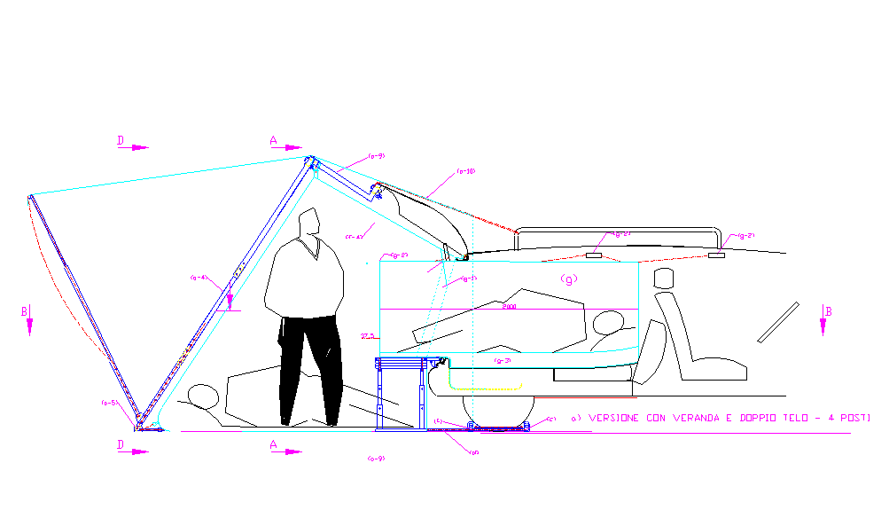
a) low car without extension; b) low car with extension (a-13) to increase the curtain space; c) tall car without extension, which obtains the same result as solution “b” without the need for the extension, taking advantage of the greater height of the car and the greater length of the tailgate. Some considerations can be drawn from observing the drawing: that the system is enhanced by tall cars, with a long tailgate and penalized by low cars, for which the expansion of the habitable space is limited; for these, a solution has been provided that allows for its expansion, represented by position “b”; that the double wedge (c) has been provided in correspondence with the rear wheels of the car to increase the possibilities of tensioning the curtain without resorting to pegs; that the tensioning ropes (f-14) are grouped together to reduce assembly times; you can also note the following details: the position of the rainwater drain of the tent roof and the car roof; the position of the PVC pipe (f-12) to limit the flow of rainwater from the roof towards the tent; the overlapping of the terminal edges (f-9) with respect to the profile of the car; In the following drawings we will always refer to solutions with low cars as they are the most common, although as mentioned above the system is enhanced by tall cars.
FIG. 7 shows a plan and longitudinal section of a car with a “Canadian” type tent. You can see: the overlapping of the flap (f-11) on the open tailgate to limit the flow of rainwater to the roof of the tent; the extension of the sleeping area (f-8) obtained directly in the tent structure and directly connected to the pocket (f-3) for extending the support surface; the alignment of the internal support surface (h) with the external support surface (h-1); the shaped profile (f-6) and the rainwater drainage holes in the drip tray (f-7).
FIG. 8 shows a plan and longitudinal section of a low car with a “Canadian” type tent, complete with sleeping area inside the passenger compartment. You can see many details already highlighted in the previous figures and the details of the connection of the internal sheet (g) with the extension (f-8) by means of the detail (g-8); this connection is eliminated only for cleaning and washing the tent to reduce assembly times.
FIG. 9 shows two longitudinal sections of a car with a “house” type tent, complete with veranda and sleeping sheet inside the passenger compartment. You can see: a) the version with double external sheet that allows for comfortable sleeping even in the tent area, bringing the total number of beds to four; b) the version with a simple veranda and structure without an extension needs no comment. Both solutions require additional telescopic structures shown in fig. 14 compared to the “Canadian” versions.
FIG. 10 shows the plan view of the telescopic structures of the versions shown in fig. 9
FIG. 11 shows the horizontal sections of the versions shown in fig. 9. It can be seen that in the “four-seater” version the feet of the people sleeping in the tent area are subjected to the extension plane (h-1); this is possible without interference with the support feet of the table (h-2), which for this reason is equipped with a single central support, as visible in fig. 12 and detail fig. 19/a.
FIG. 12 shows the cross sections of fig. 9, it can be seen: in section A-A, the view of the access to the sleeping tent (g), the table (h-2) with the central support foot from the front side; the external telescopic structure (a-14) supporting the tent; in section D-D the view of the cottage tent subjected to the external sheet (f-15); the common detail of all versions, relating to the assembly of the tensioning rope (f-14) on the profile of the car with the PVC pipes (f-9) and (f-12), the tensioning of the base rope (d) by means of the detail (b-10) (used in a secondary function, being an integral part of the translation stand of fig. 1-2-5). FIG. 12 shows the cross sections of fig. 9, it can be seen: in section A-A, the view of the access to the sleeping tent (g), the table (h-2) with the central support foot from the front side; the external telescopic structure (a-14) supporting the tent; in section D-D the view of the cottage tent subjected to the external sheet (f-15); the common detail of all versions, relating to the assembly of the tensioning rope (f-14) on the profile of the car with the PVC pipes (f-9) and (f-12), the tensioning of the base rope (d) by means of the detail (b-10) (used in a secondary function, being an integral part of the translation stand of fig. 1-2-5).
FIG. 13 is the same as Fig. 3, the rod (a-1/a) is without the winch and the profile (a-4) connecting it to the translation stand, therefore the rod (a-1) could also be used for the “tent system”. As shown, it can be used to support tents in the Canadian version; for an extended version, it uses the extension (a-13); for the house versions it is integrated with other accessories shown in fig. 14.
FIG. 14 shows additional telescopic structures and accessories, necessary for completing the proposed system already described in the table: a-12-13-14-15-16-17.
Fig. 15 shows the axonometric views of the tents in the Canadian and simple house versions. The details already described in the table and in the previous detailed figures can be identified.
Fig. 16 shows the axonometric views of the tent house with veranda, and of the additional sheet with veranda, which can be superimposed on the simple house in fig. 15/b. The details already described in the table and in the previous detailed figures can be identified.
The sheet (b) with the telescopic structures of fig. 14 could be used without the underlying awning by street vendors who use the car to display their merchandise sheltered from the elements.
Fig. 17 shows the axonometric view of the sheet inside the car. You can see: the lateral openings with zippers to access the inside also from the rear side doors of the car, as well as from the bonnet; the zipper on the wall (g-1) communicating with the front seats of the car; the trunk (g-4) shaped according to the profile of the opening space of the bonnet; the lateral and lower fabric flanges for adherence to the body of the car (g-5-6); the hole (g-6/a) for the passage of the hook for mounting the extension (h-1), the hooks (g-7) for suspending the rear end to the upper drip; the fabric flanges with tear-off felt for connection to the sheet extension (f-8).
FIG. 18 shows the details of the extension (h-1) and the support surface inside the car: you can see: the interlocking composition, without the need for tools, between the components (h-4-5-6-7-8) which determine the support and containment surface also for the slats (h-3); the creation of a space for storing material in the gap created between the floor of the car and the wooden support surface; the trapezoidal shape of the surface (h-1) which follows the shape of the sheet (g).
FIG: 19 shows the auxiliary functions that the wooden components (h) can perform to reduce the quantity of transported equipment: The support (h-2), of the extension (h-1), as already anticipated in fig.9 -11, has been designed with three telescopic supports to allow the extension to overlap with any sleeping places in the tent compartment; the lower support surface, consisting of a table that, when placed on the waterproof sheet of the floor, does not cause damage; in detail (a) it can be noted that this inverted support becomes a small rectangular table; since the size of the table is equal to that of the three slats (h-3) it was planned to couple them together to form a wooden box, useful for containing most of the system components, in particular the telescopic structures, during the storage phase: detail (c) shows the box assembled by means of two head panels (h-9) and coupling hinges, mounted at the head of each board and on the four sides of the detail (h-9); Section “A-A” and view “A” show further details of the assembled case; the same slats (h-3) and details (h-9) can be used to make sturdy stools if coupled with folding trestles, as shown in detail (b).
CAR TENT FOR SUSTAINABLE TOURISM
The writer with this project aims to provide people who make mixed use of the car (family, work, free time) with tools that enhance the possibilities of use. The idea was born by identifying in the protrusion constituted by the lock of the rear door, a valid support point for lifting and loading into the car objects of a weight greater than our modest physical possibilities; further observation of the closing space of the bonnet led to identifying in the drip tray for collecting rainwater, which follows its perimeter, a valid drainage system also for the water of a possible camping tent that could expand the living possibilities of the same bonnet; the support of the tent would be entrusted to the same tool designed for lifting the load, with the same support point. We have therefore come to put together two different arguments, but arising from a common intuition and a common basic tool that allows their realization. The basic tool designed for these functions is a telescopic metal rod (for easy transport) equipped at the upper end with a device for attaching to the bonnet lock. By mounting a small winch at the end of the telescopic rod (fig. 1), we allow a person with modest physical strength to lift heavy loads, which would require the intervention of at least two people; by coupling the rod to a track with a translation trolley and to a stand, placed in the passenger compartment, it is possible to carry out the translation and deposit of the load inside the passenger compartment and the subsequent extraction without physical effort. The load translation stand has a second possibility of use: by transforming itself, with simple assembly operations, into a load-bearing support for a convenient two-wheeled trolley, as shown in fig. 4, capable of picking up and transporting the load to the lifting point, before being used for the lifting operation itself. The small size of the equipment designed allows it to be transported by car so that it can be reused for unloading operations.
As of 2025, there does not seem to be any equipment so simple, light, cheap, and versatile that allows a person to load and unload from the car, without effort, loads of about 60 – 70 kg, even if it takes a couple of minutes to assemble and disassemble the equipment. It is nothing more than an assembly kit that can be used as an accessory to load and unload weights. The second function of “tent support”, : obviously it would have required additional accessories, but it would have allowed a more important function than the first one since, as illustrated in fig. 6, it is used to support a simple Canadian-type tent, of new conception that covers the open car bonnet, expanding the living space of the car and allowing a new rational use of the car by campers, street vendors or families for simple trips out of town. By adding an additional pole and a crosspiece, the Canadian can be transformed into a cottage version, with more space. By fitting a sheet inside the passenger compartment, with the seats folded down, two places to sleep in the car can be obtained. For medium-small cars, by adding an extension to the attachment point of the bonnet, the sleeping places can be lengthened up to two metres in length. By adding an additional telescopic structure, a veranda can be supported for the cottage version, or a second external sheet, if you want to add two more sleeping places in the tent compartment created. The “tent” function cannot be universal, but necessarily customized for each car model, but it can use the telescopic rod system designed in a universal way, which adapt to various sizes and take up little space for transport and storage. In addition to the problem of rainwater drainage in the connection section between the car and the tent, which was solved as anticipated by using (as an integral part of the system) the car’s exhaust drip tray, the problem of wind infiltration was also addressed, which was solved by inserting soft PVC pipes into the peripheral edges in contact with the body. The solution solves the problem because the PVC pipe has the right degree of flexibility to follow the shape of the body and rigidity to ensure its adherence under the action of the tensioning ropes (see fig. 12). The “tent system” can be considered an unprecedented combination of the car and the tent, simpler and cheaper than existing systems, which range from roof tents, to tent trailers, to caravans, to campers. The new invention should fit into an empty space (both commercial and functional) between the small Canadian tents, which are mounted on the ground separate from the car, and the tents mounted on the roof of the car (which have not been very successful despite the excellent workmanship of some models) combining the solidity of the car with the anti-condensation transpiration of the tent, without having to climb onto the roof or sleep on the ground, with greater safety with respect to atmospheric phenomena than is permitted by the aforementioned existing versions. In particular, in the house version, the telescopic structures could constitute a natural continuation of the Faraday cage that protects the occupants from the effects of lightning (the conditional is a must, as the appropriate checks are necessary). In addition to the problem of rainwater drainage in the connection section between the car and the tent, which was solved as anticipated by using (as an integral part of the system) the car’s exhaust drip tray, the problem of wind infiltration was also addressed, which was solved by inserting soft PVC pipes into the peripheral edges in contact with the body. The solution solves the problem because the PVC pipe has the right degree of flexibility to follow the shape of the body and rigidity to ensure its adherence under the action of the tensioning ropes (see fig. 12). The “tent system” can be considered an unprecedented combination of the car and the tent, simpler and cheaper than existing systems, which range from roof tents, to tent trailers, to caravans, to campers. The new invention should fit into an empty space (both commercial and functional) between the small Canadian tents, which are mounted on the ground separate from the car, and the tents mounted on the roof of the car (which have not been very successful despite the excellent workmanship of some models) combining the solidity of the car with the anti-condensation transpiration of the tent, without having to climb onto the roof or sleep on the ground, with greater safety with respect to atmospheric phenomena than is permitted by the aforementioned existing versions. In particular, in the house version, the telescopic structures could constitute a natural continuation of the Faraday cage that protects the occupants from the effects of lightning (the conditional is a must, as the appropriate checks are necessary).
FIG. 1 to 5 show the applications related to the “lifting system”; FIG. 6 to 19 refer to the “curtain system”; some components are common. All the elements designed are listed below in numerical order with the relative description so as not to repeat them later in the illustrations of the drawings:
(a) telescopic rod:
(a-1) telescopic rod structure made up of three elements of tubular galvanized steel (or similar) with a decreasing section from top to bottom, equipped with holes for mounting accessories and for telescopic adjustment of the length, variable based on the height of the vehicle to be served. To ensure greater rigidity of the rod, the length will be adjusted by at least two steel pins for each section of the rod, secured with quick-assembly UNI 3545 shaped cotter pins. The upper end of the rod will be rigidly fixed to the lock structure, as shown in detail “A” in fig.1, so as not to stress the same to tip bending, but to transmit the modest induced stress only to the fixing bolts of the structure. Let us see in detail the extent of this stress: suppose that the load to be lifted is 70 kg and the inclination of the rod is 300 with respect to the vertical. As a result of the decomposition of the forces we will have a force that will act along the axis of the rod structure with a compressive bending stress and another that will act on the upper support point, stressing the fixing bolts of the lock in shear.Il valore della Ia forza è il seguente: 70 x cos 300 = 70 x 0,866 = 60,62 kg = 606,2 N;
the value of the IIa force is the following: 70 x sin 300 = 70 x 0.50 = 35 Kg = 350 N.
If we consider that this stress is distributed over at least two bolts, we realize the inconsistency of the stress itself, considering that bolts with a minimum resistance class (3.6 of the UNI EN 20898 standard) have a nominal breaking load of 300 N/mm2; therefore a modest M5 threaded bolt with a resistant section of 14.2 mm2 has a minimum breaking load of 4690 N. Since this is not the place for the structural calculation of the rod, we only wanted to demonstrate that with the proposed solution it will not be possible in any way to cause damage to the structure of the car lock on which it is essential to lean.
(a-1/a) telescopic pole identical to the previous position but without winch and appendix for connection to the translation stand, to be used only for the “awning system”, see fig.13.
(a-2) cable winch with adequate capacity, with manual crank control, equipped with three working positions: lifting, lowering, load support, built according to CE regulations.
(a-3) lifting hook.
(a-4) appendix for connection to the translation stand (not necessary in the awning system, but does not hinder its use), consisting of a perforated “c” profile to allow height adjustment of the stand connected to it.
(a-5) articulated support plate. (a-6) perno di aggancio alla serratura del cofano, con estremità opposta a occhiello eventuali tiranti a fune.
(a-7) eccentric bracket with adjustment slot.
(a-8) locking screw and wing nut.
- Details shown in fig.3-5:
(a-9) ISO 3266 galvanized circular eyebolt.
(a-10) rod coupling bracket for tripod function, consisting of a ring made with a steel round bar divided into three sectors arranged at 120, each of which carries two shaped and drilled plates for coupling to the eyebolt (a-9) specifically designed at the end of the rod (a-1).
(a-11) steel pin with ISO 3545 shaped quick split pin. - Details shown in fig.13:
(a-12) intermediate element for connecting the car bonnet to the telescopic crosspiece (a-14) in the “house awning without extension” version.
(a-13) intermediate element for connecting the car bonnet to the telescopic rod (a-1/a) for the “extended Canadian” version, or to the telescopic crosspiece (a-14) in the “extended house awning” version.
(a-14) telescopic crosspiece for supporting the awning in the “house” versions, made up of three elements of galvanised steel tubing (or similar) with a decreasing section towards the outside, equipped with holes for mounting accessories and for telescopic adjustment of the length, variable based on the width of the car to be served. To ensure greater rigidity of the rod, the length will be adjusted by at least two steel pins for each section of the rod, secured with quick-assembly UNI 3545 shaped cotter pins.
(a-15) telescopic rod for supporting the crosspiece (a-17), made up of three elements of tubular galvanized steel (or similar) with increasing section from top to bottom, equipped with holes for assembly and for telescopic adjustment of the length. To ensure greater rigidity of the rod, the length will be adjusted by at least two steel pins for each section of the rod, secured with quick-assembly UNI 3545 shaped cotter pins.
(a-16) rod connection bracket (a-1/a) to the rod (a-15) by means of pins with quick-assembly ISO 3545 cotter pin.
(a-17) telescopic crosspiece for supporting the veranda in the cottage version with identical construction characteristics to (a-14). - Details shown in fig.1-2-4-5:
(b) load transfer stand, designed to accompany the lifted load inside the passenger compartment of the car; to be easily transportable it has been designed to be completely articulated and removable, as shown in fig. 4; it can be transformed into a convenient two-wheel trolley, capable of picking up and transporting the load to the lifting point, before being used for the lifting operation itself and above all it is easily transportable in the car to be reused for unloading operations.
(b-1) connection element to the telescopic structure, consisting of two parallel plates, between which the hook and the lifting rope can easily pass; it also constitutes the connection element to the trolley base (b-15), to carry out the auxiliary transformation of the structure into a trolley, see fig. 4.
(b-2) track for sliding the translation trolley.
(b-3) 4-wheeled trolley, equipped with a circular eyebolt at the bottom.
(b-4) steel pin to stop the trolley.
(b-5) galvanized steel snap hook for load translation.
(b-6) galvanized steel snap hook for load support.
(b-7) load stop pin to change trolley function.
(b-8) n.2 articulated arms supporting the trestle track, hinged by means of a plate at the end of the track and locked by a screw in the working position.
(b-9) n.2 telescopic feet for the trestle, hinged by means of a plate at the end of the articulated arms (b-8) and automatically locked in the working position by a gravity pin: without lifting the pin it is not possible to close the foot.
(b-10) articulated foot support plate.
(b-11) hinge between the arm (b-8) and the foot (b-9).
(b-12) gravity pin, which allows the foot (b-9) to close only after it has been lifted.
(b-13) hinge between the arm (b-8) and the track (b-2).
(b-14) locking screw for the translation stand in the working position.
(b-15) base for a two-wheel trolley, designed to be mounted on the element (b-1) of the translation stand and together with the same and connected components (b-2 and b8), to form a complete trolley for lifting and transporting materials, see fig.4.
(c ) wedge for the car wheel, made of wood or plastic material, equipped with a metal plate screwed onto it to which the ropes constituting the tie rods of the “curtain system” and “load lifting” are tied. In the curtain system, two wedges per wheel are used to increase the tensioning possibilities and to allow the assembly of a lower spacer of the rope (d), which aligns it with the profile of the car: the detail is visible in a detail of fig. 12;
(d) nylon rope for fixing the plate (a-5) to the floor, of the lower edges of the curtain, connected to the wedges (c );
(e) nylon rope for locking the rod (a-1) to the hinges for opening the car bonnet.
(f) curtain details, shown in fig. 6-7-8-9-10-11-14-15-16:
(f-1) curtain wall on the entrance side, with zip.
(f-2) rear curtain wall on the car side.
(f-3) containment pocket for the bonnet floor extension (the pocket and the wooden extension are trapezoidal in shape to facilitate assembly and disassembly operations);
(f-4) tent roof.
(f-5) shaped lower profile for connecting the tent to the car, equipped with a soft PVC tube with internal cord that allows adhesion to the body, limiting atmospheric infiltrations.
(f-6) upper profile shaped as above.
(f-7) rainwater drainage holes of the connection (f-6) in the drip tray of the car bonnet.
(f-8) extension of the bonnet overnight cover, overlapping the pocket (f-3), equipped with a Velcro zip on the four internal sides for connection to the flanges (g-8) of the cover.
(f-9) terminal edge supporting the shape of the body incorporating (bagged) at the end, for the entire length, a soft PVC tube (or similar) for adhesion to the profile of the body, limiting atmospheric infiltrations.
(f-10) double-walled shaping in correspondence with the tailgate support pistons, necessary in some types of cars.
(f-11) cover flap with tie rods, foldable on the tailgate to limit the flow of water onto the roof of the tent.
(f-12) PVC tube soft, with internal cord, positioned on the roof of the car to limit the flow of rainwater in the area connecting the car to the awning.
(f-13) awning in the house versions.
(f-14) awning tensioning tie rods.
(f-14/a) tailgate locking tie rods.
(g) details of the car’s internal canvas, shown in fig. 8-9-11-12-17:
(g-1) rear wall with communication zip.
(g-2) side walls with access zips.
(g-3/a/b) roof / bottom.
(g-4) trunk shaped according to the profile of the bonnet opening.
(g-5) fabric side flanges, equipped with eyelets for tensioning cords, designed to adhere to the profile of the body: they will be subjected to the details (f-9) to limit air infiltration and will cover the rainwater drainage channel without limiting the flow of the same.
(g-6) fabric lower flange, equipped with eyelets for tensioning cords, designed to adhere to the profile of the body to limit air infiltration: it will be drilled (g-6/1) to allow the attachment of the extension (h-1) to the bonnet compartment.
(g-6/a) extension mounting hook passage hole (h-1).
(g-7) upper end support hooks of the sheet, designed to attach to the profile of the upper drip tray: they will be made of stainless steel, with one side sewn to the sheet and the other equipped with a rubber pad that rests on the body, without crushing the seal.
(g-8) n. 4 fabric flanges edged at the end with felt for a Velcro zip, designed to connect to the canvas extension (f-8) incorporated in the tent structure. The coupling between the f-8 and g-8 flanges is permanent to reduce assembly times, they should only be broken out for cleaning and washing operations;
(h) details of the hood extension and wooden support surface, shown in fig. 7-8-9-10-11-17-18-19:
(h-1) wooden extension, designed to extend the hood interior: it will be customized for each type of vehicle, in general it will have the following characteristics: slightly trapezoidal shape to be easily inserted and removed from the fabric pocket (f-3) incorporated in the tent; it will be hooked into the fixed part of the hood closing zip and at the bottom, it will rest on the body, in the lower water drainage channel, by means of two stops with ends equipped with a rubber plug; further and more substantial support will be provided by the table (h-2) below.
(h-2) wooden table shown in (fig.19/a), designed to support the extension (h-1), to be used as a rectangular camping table combined with stools (fig. 19/b) and as an element of the containment box for the system components (fig.19/c): it will be equipped with coupling hinges (h-2/1), three hinged feet (h-2/4) and telescopic feet (h-2/3) to perform the functions described above.
(h-3) central slats for wooden support surface, designed to be used also for the formation of any stools, in combination with the detail (h-10) and as elements of the containment box for the system components (fig.19/c), using the coupling hinge (h-2/1).
(h-4) wooden stringers to support the slats, also designed to level the support surface: they will be made in two pieces, to be easily contained in the trunk or in the case (fig.19/c); they will be equipped with notches for the assembly interlocking with (h-7 and 8) which will block their position.
(h-5) rear terminal slat, designed to follow the internal shape of the trunk compartment and distance the parts (h-4).
(h-6) front terminal slat, designed to complete the length of the compartment and distance the parts (h-4).
(h-7) right side slat, designed to complete the width of the compartment; block the parts (h-4) by means of their supports equipped with interlocking notches; contain the slats (h-3) laterally simply resting on the parts (h-4).
(h-8) left side slat, as above.
(h-9) wooden element equipped on the 4 sides with coupling hinges (h-9/1), designed to be used as a closing head of the containment box (fig.19/c) and as a stool in combination with the part (h-10).
(h-10) foldable metal stand usable for the creation of stools in combination with the parts (h-3 and h-9): it will be equipped with coupling pins for the interlocking in the holes provided in the parts themselves and a nylon band (h-10/1) to contain the degree of opening.
The FIG. 1 to 5, are dedicated to the representation of the “lifting system”:
FIG. 1 shows a typical section of a car with the application of the load lifting and transfer equipment. The tool allows the aforementioned loads to be easily lifted, which generally do not exceed 60-70 kg, and facilitates their depositing and extraction from the passenger compartment with the help of a small winch with a crank handle (a-2). The telescopic rod (a-1) rests on the ground and hooks onto the structure of the tailgate lock by pushing the pin (a-6) upwards which releases the lock, the eccentric bracket (a-7) which blocks the lock to the rod is screwed on in order to avoid bending stresses on the rod, it is tied with a rope to the opening hinges of the tailgate itself, and below, to the wedges (c) placed under the rear wheels of the car; subsequently, the load transfer stand (b) is mounted, which is hooked on one side to the rod with the element (b-1), by means of a steel pin, while the opposite side rests on the internal floor of the vehicle by means of the telescopic feet (b-9 / b-10). The load is lifted by the hook (a-3) which passes through the two load-bearing plates (b-1). When the high position is reached, the load is stopped, the translation trolley (b-3) is brought close to the locking pin (b-4), it is hooked with the translation snap hook (b-5) to the rope and the support snap hook (b-6) to the load; the support rope is loosened by turning the winch crank in the opposite direction and making all the weight rest on the trolley (b-3), the suspended load is pushed inside the passenger compartment; Once you have reached the unloading point, lock the trolley with the pin (b-7), tighten the rope by slightly lifting the load with the winch, release the snap hook (b-6), place the load on the floor by operating the winch, finally release the snap hook (b-5) and the hook (a-3). To unload, carry out the above operations in reverse: hook the load (a-3), hook the rope with the snap hook (b-5), lift the load, loosen the rope with the winch (a-2), remove the pin (b-7), move the load outside the vehicle compartment, deposit the load on the ground with the winch. You can then dismantle the translation structure, transform it into a trolley and transport the load to its destination. Fitting the lifting structure to the vehicle takes no more than 2 minutes and the time can be reduced if the telescopic structures are already adjusted to the working height of your vehicle.
FIG. 2 shows the loading system seen from the top and rear of the vehicle with some slightly enlarged details. You can see: view “A” and the horizontal section with the positioning of the stand inside the passenger compartment and the locking system with the ropes (d) and (e); detail “A”, the hinge (b-11) between the arm (b-8) and the foot (b-9) and the position of the gravity pin (b-12); detail “B”, the hinge (b-13) between the arm (b-8) and the track b-2 and the position of the locking screw (b-14); detail “C”, the articulated plate (a-5) with the rope (d) connecting it to the wedges “c” placed under the wheels of the vehicle; detail “D”, the support plate b-10 of the foot b-9.
FIG. 3 shows an axonometric view of the telescopic rod with winch and accessories. You can see: the rod extended, in working position and shortened for storage or transport; the details (a-9, a-10, a-11), necessary for a further, possible use of the rod as a tripod.
FIG. 4 shows an axonometric view of the gantry structure for the translation of the load inside the passenger compartment. You can see: “A”, the articulated structure in the closed position for storage or transport (the open position is visible in fig. (1 and 2); “B”, the structure without the details (b-9 and b-10) to be transformed into a trolley; “C”, the structure transformed into a transport trolley, useful for moving luggage, household appliances, bags, work equipment, etc.
FIG. 5 shows the use of the telescopic rod equipped with a winch with the translation stand described above, coupled with two additional telescopic rods to form an easy-to-transport tripod with many possible uses (think of workers working in road manholes, lifting through attic trapdoors or simply handling equipment during assembly or painting phases in rooms without lifting equipment. You can see: the telescopic feet (b-9) longer than the version used for loading the vehicle; the cable connections “d” of the support plates (a-5); the enlarged detail of the upper connection with the particulars (a-9, a-10, a-11).
FIG. 6 to 19 are dedicated to the representation of the “curtain system”:
FIG. 6 shows three typical side views of the application of a curtain to the hood of cars:
a) low car without extension; b) low car with extension (a-13) to increase the curtain space; c) tall car without extension, which obtains the same result as solution “b” without the need for the extension, taking advantage of the greater height of the car and the greater length of the tailgate. Some considerations can be drawn from observing the drawing: that the system is enhanced by tall cars, with a long tailgate and penalized by low cars, for which the expansion of the habitable space is limited; for these, a solution has been provided that allows for its expansion, represented by position “b”; that the double wedge (c) has been provided in correspondence with the rear wheels of the car to increase the possibilities of tensioning the curtain without resorting to pegs; that the tensioning ropes (f-14) are grouped together to reduce assembly times; you can also note the following details: the position of the rainwater drain of the tent roof and the car roof; the position of the PVC pipe (f-12) to limit the flow of rainwater from the roof towards the tent; the overlapping of the terminal edges (f-9) with respect to the profile of the car; In the following drawings we will always refer to solutions with low cars as they are the most common, although as mentioned above the system is enhanced by tall cars.
FIG. 7 shows a plan and longitudinal section of a car with a “Canadian” type tent. You can see: the overlapping of the flap (f-11) on the open tailgate to limit the flow of rainwater to the roof of the tent; the extension of the sleeping area (f-8) obtained directly in the tent structure and directly connected to the pocket (f-3) for extending the support surface; the alignment of the internal support surface (h) with the external support surface (h-1); the shaped profile (f-6) and the rainwater drainage holes in the drip tray (f-7).
FIG. 8 shows a plan and longitudinal section of a low car with a “Canadian” type tent, complete with sleeping area inside the passenger compartment. You can see many details already highlighted in the previous figures and the details of the connection of the internal sheet (g) with the extension (f-8) by means of the detail (g-8); this connection is eliminated only for cleaning and washing the tent to reduce assembly times.
FIG. 9 shows two longitudinal sections of a car with a “house” type tent, complete with veranda and sleeping sheet inside the passenger compartment. You can see: a) the version with double external sheet that allows for comfortable sleeping even in the tent area, bringing the total number of beds to four; b) the version with a simple veranda and structure without an extension needs no comment. Both solutions require additional telescopic structures shown in fig. 14 compared to the “Canadian” versions.
FIG. 10 shows the plan view of the telescopic structures of the versions shown in fig. 9
FIG. 11 shows the horizontal sections of the versions shown in fig. 9. It can be seen that in the “four-seater” version the feet of the people sleeping in the tent area are subjected to the extension plane (h-1); this is possible without interference with the support feet of the table (h-2), which for this reason is equipped with a single central support, as visible in fig. 12 and detail fig. 19/a.
FIG. 12 shows the cross sections of fig. 9, it can be seen: in section A-A, the view of the access to the sleeping tent (g), the table (h-2) with the central support foot from the front side; the external telescopic structure (a-14) supporting the tent; in section D-D the view of the cottage tent subjected to the external sheet (f-15); the common detail of all versions, relating to the assembly of the tensioning rope (f-14) on the profile of the car with the PVC pipes (f-9) and (f-12), the tensioning of the base rope (d) by means of the detail (b-10) (used in a secondary function, being an integral part of the translation stand of fig. 1-2-5). FIG. 12 shows the cross sections of fig. 9, it can be seen: in section A-A, the view of the access to the sleeping tent (g), the table (h-2) with the central support foot from the front side; the external telescopic structure (a-14) supporting the tent; in section D-D the view of the cottage tent subjected to the external sheet (f-15); the common detail of all versions, relating to the assembly of the tensioning rope (f-14) on the profile of the car with the PVC pipes (f-9) and (f-12), the tensioning of the base rope (d) by means of the detail (b-10) (used in a secondary function, being an integral part of the translation stand of fig. 1-2-5).
FIG. 13 is the same as Fig. 3, the rod (a-1/a) is without the winch and the profile (a-4) connecting it to the translation stand, therefore the rod (a-1) could also be used for the “tent system”. As shown, it can be used to support tents in the Canadian version; for an extended version, it uses the extension (a-13); for the house versions it is integrated with other accessories shown in fig. 14.
FIG. 14 shows additional telescopic structures and accessories, necessary for completing the proposed system already described in the table: a-12-13-14-15-16-17.
Fig. 15 shows the axonometric views of the tents in the Canadian and simple house versions. The details already described in the table and in the previous detailed figures can be identified.
Fig. 16 shows the axonometric views of the tent house with veranda, and of the additional sheet with veranda, which can be superimposed on the simple house in fig. 15/b. The details already described in the table and in the previous detailed figures can be identified.
The sheet (b) with the telescopic structures of fig. 14 could be used without the underlying awning by street vendors who use the car to display their merchandise sheltered from the elements.
Fig. 17 shows the axonometric view of the sheet inside the car. You can see: the lateral openings with zippers to access the inside also from the rear side doors of the car, as well as from the bonnet; the zipper on the wall (g-1) communicating with the front seats of the car; the trunk (g-4) shaped according to the profile of the opening space of the bonnet; the lateral and lower fabric flanges for adherence to the body of the car (g-5-6); the hole (g-6/a) for the passage of the hook for mounting the extension (h-1), the hooks (g-7) for suspending the rear end to the upper drip; the fabric flanges with tear-off felt for connection to the sheet extension (f-8).
FIG. 18 shows the details of the extension (h-1) and the support surface inside the car: you can see: the interlocking composition, without the need for tools, between the components (h-4-5-6-7-8) which determine the support and containment surface also for the slats (h-3); the creation of a space for storing material in the gap created between the floor of the car and the wooden support surface; the trapezoidal shape of the surface (h-1) which follows the shape of the sheet (g).
FIG: 19 shows the auxiliary functions that the wooden components (h) can perform to reduce the quantity of transported equipment: The support (h-2), of the extension (h-1), as already anticipated in fig.9 -11, has been designed with three telescopic supports to allow the extension to overlap with any sleeping places in the tent compartment; the lower support surface, consisting of a table that, when placed on the waterproof sheet of the floor, does not cause damage; in detail (a) it can be noted that this inverted support becomes a small rectangular table; since the size of the table is equal to that of the three slats (h-3) it was planned to couple them together to form a wooden box, useful for containing most of the system components, in particular the telescopic structures, during the storage phase: detail (c) shows the box assembled by means of two head panels (h-9) and coupling hinges, mounted at the head of each board and on the four sides of the detail (h-9); Section “A-A” and view “A” show further details of the assembled case; the same slats (h-3) and details (h-9) can be used to make sturdy stools if coupled with folding trestles, as shown in detail (b).
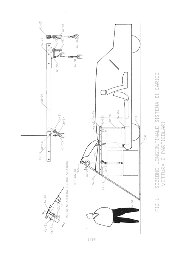
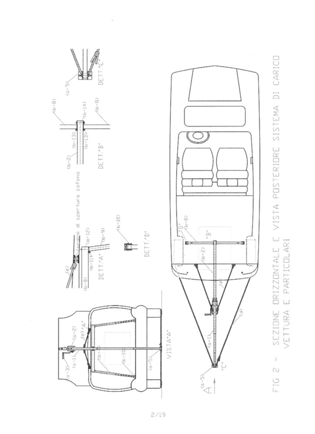
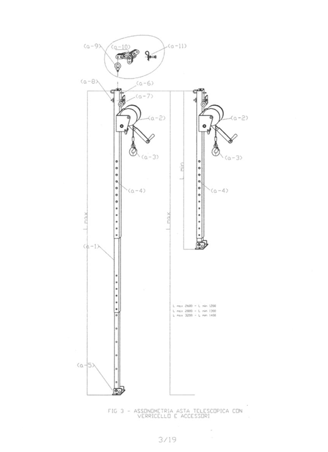
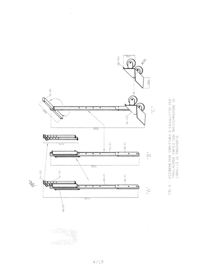
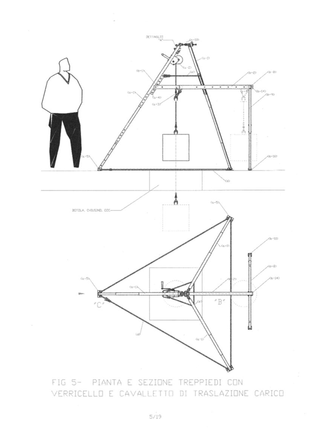
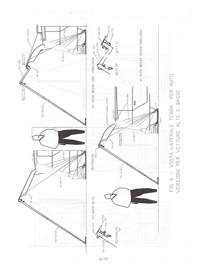
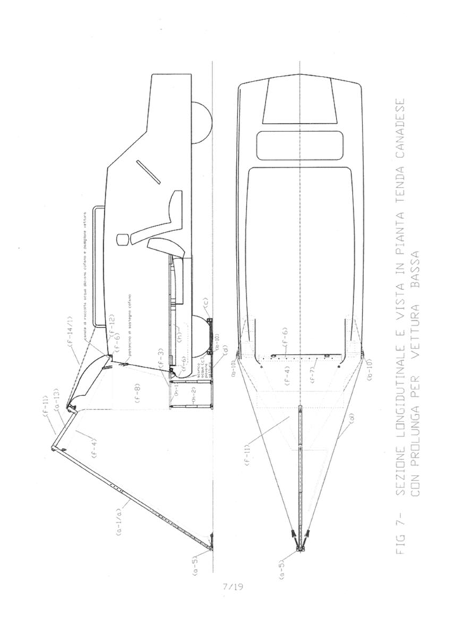
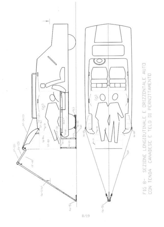
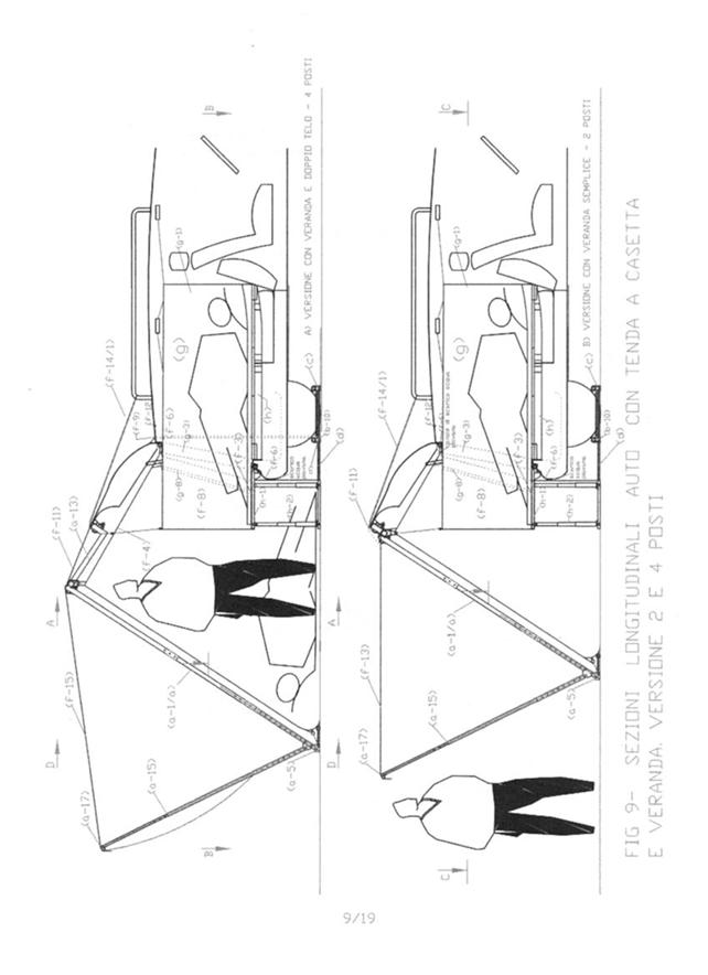
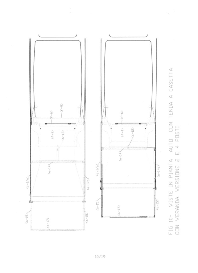
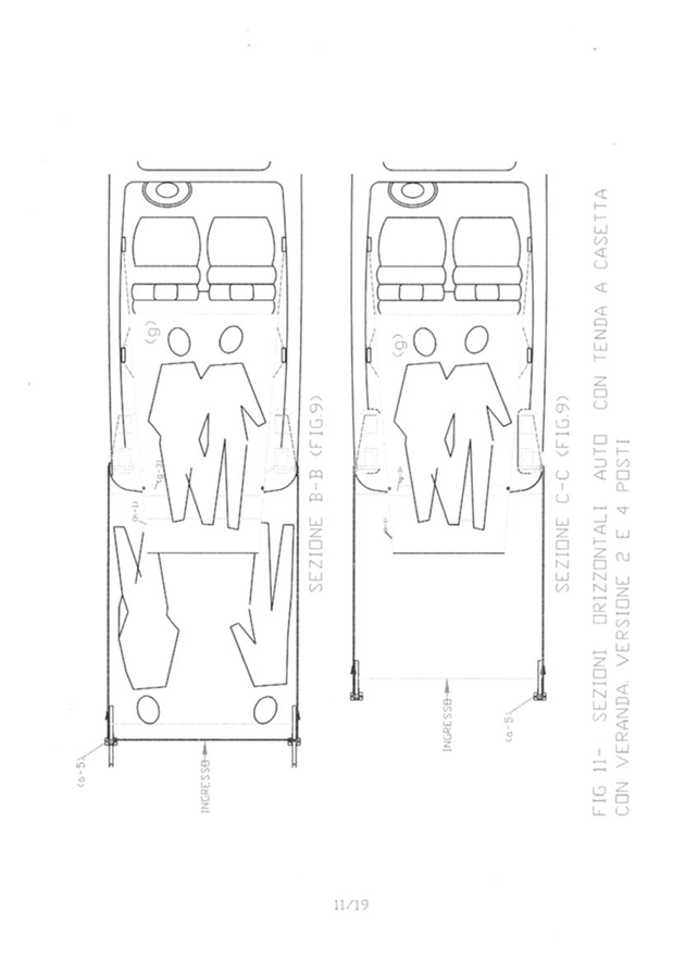
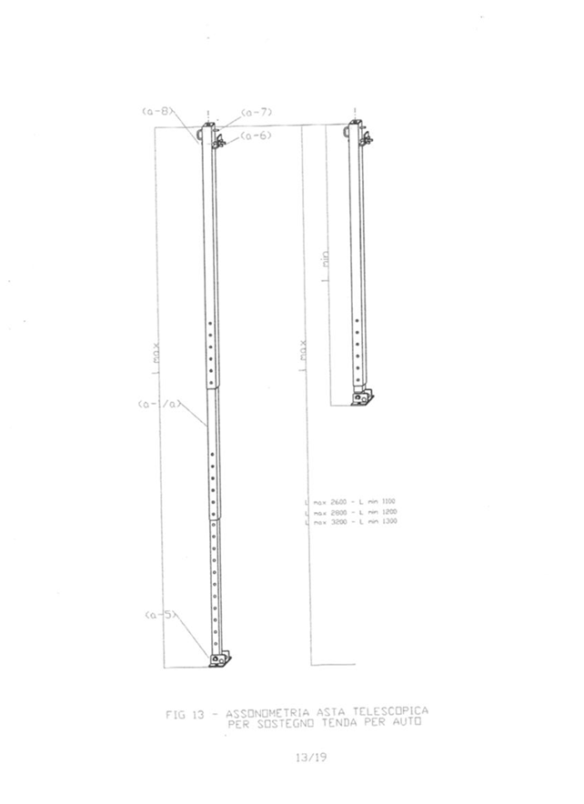
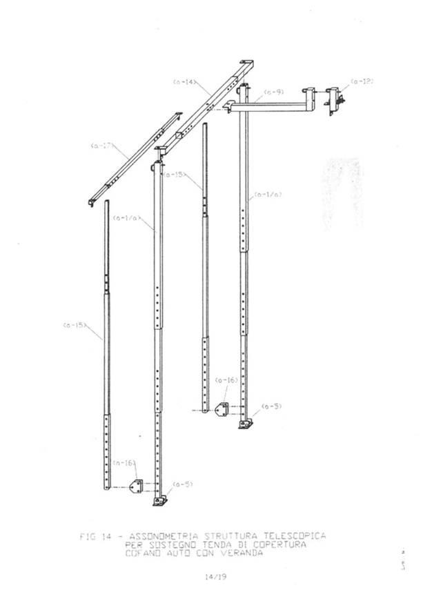
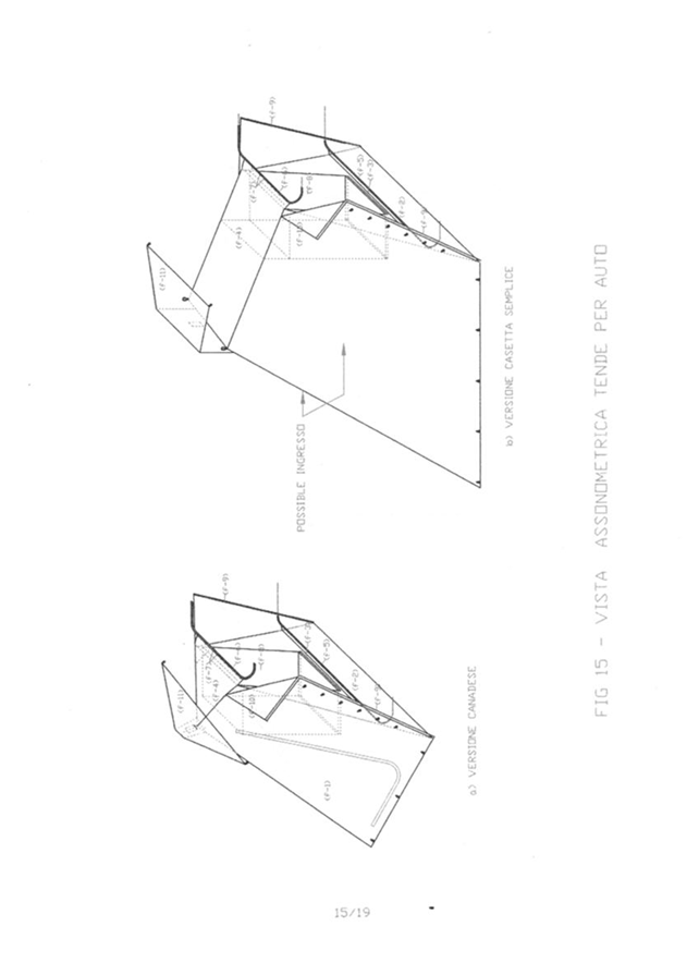
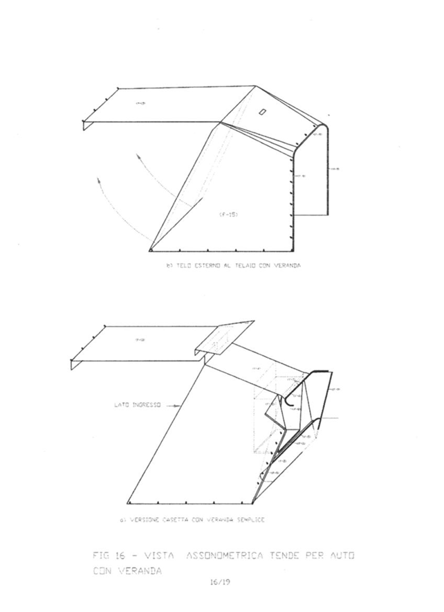
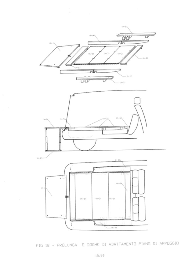

Conclusions
Obviously, the tent system illustrated above only wants to demonstrate that sustainable development cannot be improvised but is designed globally in small steps by developing all the details that slowly find their place. The car tent illustrated above would have been very useful if a small company had invested in the modular construction of the accessories and built to measure for individual car models through an internet advertisement. These things cannot be done by the inventor who has the duty to develop other ideas and make them available to people who do not know how to design. For these reasons, inventors must be granted intellectual property, not industrial property. Industrial property must be granted to the manufacturer who purchases the national or international production rights. I don’t remember how long it took me to develop this project but I certainly worked on it for two or three months. Instead, I remember well that I spent 400 euros to file the patent because in 2007 there was no electronic filing which today would cost 50 euros. In 2007, the bureaucrats of the patent offices counted the number of pages filed and the number of claims. Their calculation required the payment of four hundred euros just for the production of the system in Italy which obviously, did not find interlocutors, like the other forty inventions of the undersigned, which did not even find interlocutors. When in 2016 I invented the autonomous energy generator that extracts clean energy from the environment and I mounted it on the same car that in 2007 I had used to pitch the tent, I closed the system opened in 2007 creating a sustainable mobile system that if it had worked, would have allowed us to survive even at the poles and in the deserts without fuels since the current heat pumps, already existing, do not need fossil energy to work but only electricity. But all the capitalist and communist world governments have continued to support the current car manufacturers with incentives and funding to continue using heat as an energy source by improving the quality of fuels and using purification devices such as catalytic converters, increasing the cost of transportation, without completely solving the problem of pollution and global warming.
All this would be ridiculous if I were right, because on planet Earth, energy is everywhere. I realized this by chance after having filed four international patents on the cleaning of fossil energy that no government and no multinational has financed, where I had planned artificial rain on calcareous materials to reduce CO2 and combustion oxides by producing carbonates in the water. To reduce the costs of this simple process I invented the submerged hydroelectric system that within the same basin, large or very small, by putting in series a pump that pumps in the direction of the gravitational force and immediately below it an identical pump connected to a current generator that works as a turbine, I realized that the current generator produces much more energy than that absorbed by the pump motor for the simple fact that the pump works in the gravitational direction and exploits the hydrostatic head and transfers the kinetic energy to the twin pump that works as a turbine, which, by turning the shaft of the electric current generator, simultaneously produces both the part of the energy due to the potential energy and the part of the energy due to the kinetic energy supplied by the pump motor. From this intuition was also born compressed hydroelectric energy and many other strategic and interactive inventions that would have simplified and shortened the purification and energy processes, which official science pretended not to understand in order to continue to heat the planet at the service of governments and multinationals. The simplest invention is precisely the energy-autonomous current generator that no country has financed. Which could protect even the poor and bombed people from the cold and heat, but we do not know for sure because the inventor of the compressed hydroelectric system was left alone, although he spent over 20,000 euros to pay for national and international patent deposits, in order to seek public and private interlocutors, respecting the laws that the United Nations have spread to regulate world development through the WIPO (World Intellectual Property Organization) which is precisely, a body of the United Nations. WIPO, instead of helping inventors, forces them to pay taxes that they should not pay, as writers, musicians, artists in general do not pay, who do not create any direct scientific, technological and economic development. This is the reason why inventors not linked to the centers of political and economic power on planet Earth do not exist. If they did, global warming would not have even started. Today it cannot be stopped for the same reason. In my article https://www.spawhe.eu/the-spawhe-rhyme-and-the-map-of-the-website/ I make a complete list of unfunded sustainable inventions that would have prevented and purified the wrong inventions that have produced global warming.
The figures below show the hydroelectric car that could allow sustainable tourism in the future; the electricity generator that could allow climate survival even in a tent by coupling it with a heat pump, which has already been on the market for at least thirty years.
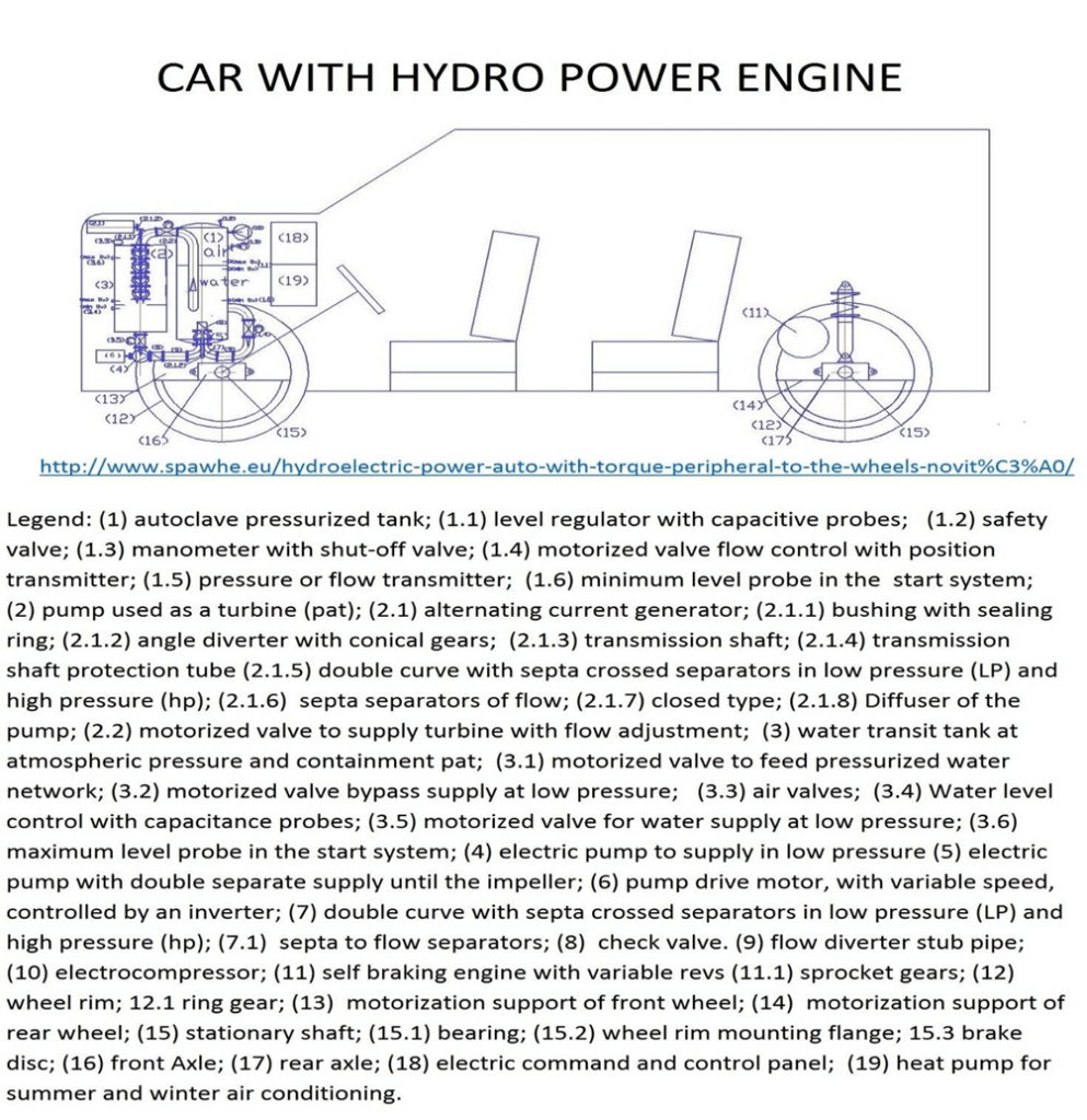
The figure below represents a sustainable swimming pool with rainwater coupled with a tank with a submerged hydroelectric system that with the reported scheme sized for each individual condominium of the communist and capitalist countries, in every corner of the Earth, would produce all the electrical energy needed without the need for current electrical distribution networks and consequently, without the need for current thermal power plants, nuclear power plants, solar panels and wind turbines, which would combine the useful, the enjoyable, the economy, also being able to be covered and heated in the winter months. This system is nothing more than a miniature of what is described in the article we speak scientifically of the disaster of the Bargi power plant, which is shown in the following drawing 20.04.2024 https://www.spawhe.eu/lets-talk-scientifically-about-the-italian-disaster-of-the-bargi-hydroelectric-power-plant/.
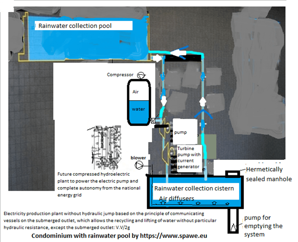
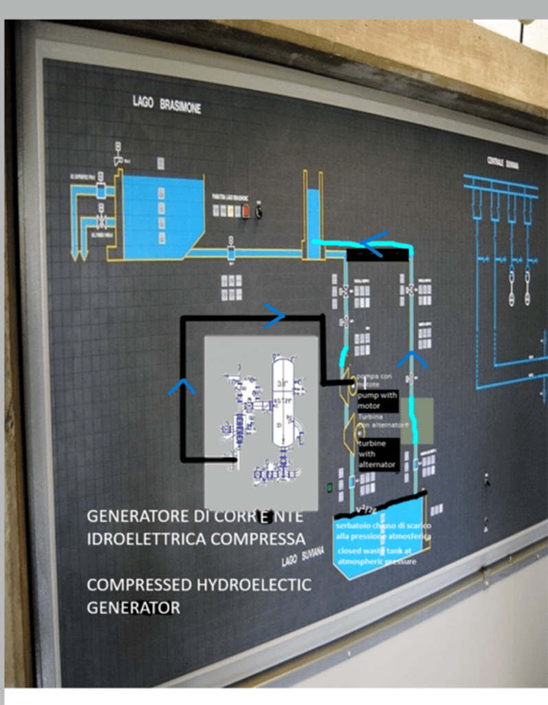
The submerged hydroelectric system reported above would already be sufficient to solve the current global energy and climate problems, being able to be built in any size to power industrial and civil plants in every corner of the Earth, from Greenland to the deserts by coldly extracting energy from the terrestrial environment. However, it is essential to also build the compressed hydroelectric system, which would allow the production of energy for small and large mobile plants that are energy autonomous on land, in aeronautics, space, marine and submarines, described after the following figure.
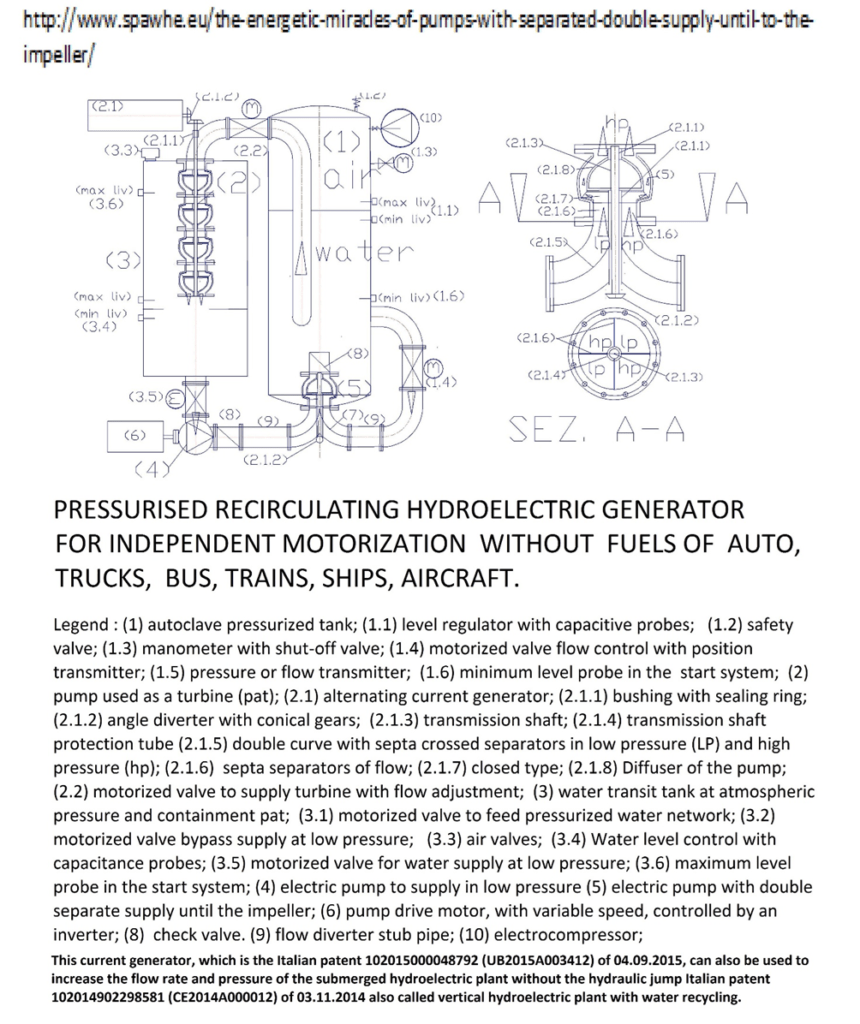
Below are the main articles that deal with these topics still misunderstood by public and private science worldwide that has uselessly created global warming.
30.06.2016 https://www.spawhe.eu/autoclave-system-for-water-pumping-hydroelectric-energy-producer/,
31.08.2016 https://www.spawhe.eu/pumps-and-turbines-with-separated-double-supply-until-to-the-impeller/
10.11.2016 https://www.spawhe.eu/pressurised-submerged-hydroelectric-plants-in-basins-with-lifting-and-oxygenation/,
11.11.2016 https://www.spawhe.eu/pressurised-submerged-hydroelectric-plants-in-wells-with-lifting-and-oxigenation/
14.01.2017 https://www.spawhe.eu/hydroelectric-power-auto-with-peripheral-torque-to-the-wheels/,
14.01.2017 https://www.spawhe.eu/hydroelectric-power-auto-with-peripheral-torque-to-the-wheels/,
31.07.2017 https://www.spawhe.eu/aerospatial-pressurized-hydroelectric-transport-system-with-turbofan-and-compressed-air-injection/
04.09.2017 https://www.spawhe.eu/the-interactive-energy-inexhaustible-and-protective-of-the-environment-unwanted-by-science-and-governments/,
30.09.2017 https://www.spawhe.eu/the-world-revolution-of-transportation-unwanted-by-manufacturers-by-science-by-the-governments-and-others/,
10.11.2017 https://www.spawhe.eu/cop-23-the-mysteries-of-the-interactive-energy-and-depurations-hided-by-the-institutions/,
29.12.2017 https://www.spawhe.eu/compressed-air-is-much-more-powerful-practice-and-economic-of-hydrogen/,
31.05.2018 https://www.spawhe.eu/artificial-heart-oxygenator-of-blood-energyically-autonomous/,
30.05.2019 https://www.spawhe.eu/the-interactive-energy-that-the-current-generations-do-not-understand-are-the-best-resource-of-future-generation/,
31.01.2020 https://www.spawhe.eu/aerospace-and-submarine-transport-system-with-interactive-primary-and-inductive-linear-motors/,
31.01.2020 https://www.spawhe.eu/flying-and-floating-cars-with-interactive-global-linear-motors-and-thrust-of-newton-and-lorentz/,
01.02. 2021 https://www.spawhe.eu/open-letter-to-mr-elon-musk-who-promised-100-million-dollars-to-those-who-manage-to-capture-co2-from-the-atmosphere/,
29.07.2021 https://www.spawhe.eu/interstellar-dust-capture-system-and-space-environmental-plants/,
29.07.2021 https://www.spawhe.eu/from-the-earth-beyond-the-moon-colonizing-space-with-compressed-hydroelectromagnetic-energy-unknown-to-terrestrial-science/
12.05.2023 https://www.spawhe.eu/flying-containers-for-rescuing-migrants-and-extinguishing-fires-without-using-fuel/,
These systems that public and private science worldwide still pretend not to understand, if they had been financed, tested and implemented throughout the world, would probably have already solved simultaneously, environmental, energy, economic, social, health problems and would also extend human life. It is no coincidence that my artificial heart oxygenator of the blood energetically autonomous, is nothing but the miniature of the compressed hydroelectric system, which the undersigned has virtually mounted in all means of transport.
(31.05.2018 https://www.spawhe.eu/it/cuore-artificiale-ossigenatore-del-sangue-autonomo-energeticamente/).
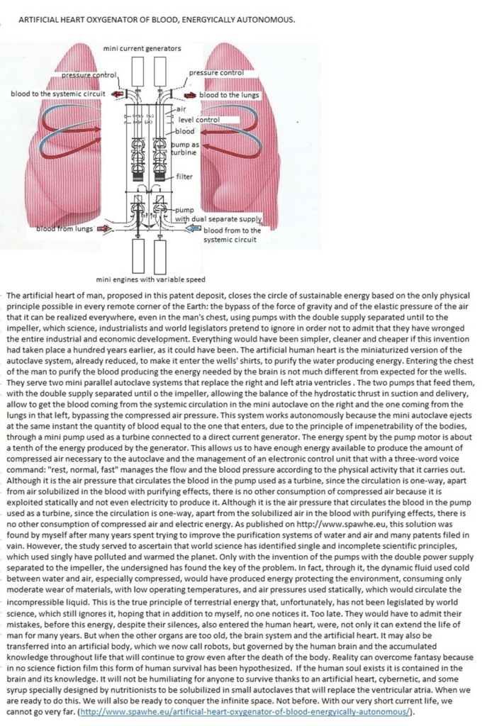
Water is essential for human life, animals and plants. The human body at birth has 75-85% water, which drops to 60% in adults and 50-44% in the elderly. In plants it is 90%; the planet is covered by 71% water, but the percentage actually covered by water is 97% because in addition to the oceans, 2.1% is found in the polar ice caps and glaciers, while only 0.65% is concentrated in rivers, lakes, aquifers and underground water and in the atmosphere, available to all living beings. However, on planet Earth even today, over a billion people still do not have access to drinking water, due to poor structural water designs by men. If you read my curriculum vitae (https://www.spawhe.eu/english-curriculum-vitae/) you can see that most of my life I have spent installing water systems designed by world public bodies, which have not taken into account the scientific organization of natural work, which entrusts water with the task of transporting fluid dynamics and electromagnetic force through ions (OH-) (H+) both in liquid and vapor form. It was no coincidence that my inventions of submerged and compressed hydroelectricity that terrestrial science still pretends not to understand were born from my attempt to clean fossil energy with logical artificial rains on calcareous materials to produce carbonates, phosphates, nitrates, sulphates in the water to be sent to the seas, while the science of governments and multinationals have spent hundreds of billions to hide CO2 underground with the C.C.S. system. Despite the obvious failure of the CCS system, ten years after the invention of hydroelectric energy without the hydraulic jump, I am still alone, with my modest pension, at seventy-six years old, trying to make demonstrative prototypes of my inventions, due to the lack of interlocutors. It is an obvious conflict of interest of the world’s ruling classes, but also an obvious scientific and organizational error of world work, because there is nothing that can be more economical and efficient than compressed air as an energy source and water as an energy vector that are not consumed and can produce energy at all hours of the day and night without dispersing either the energy source (compressible) or the energy vector (incompressible). The entire world science is making itself ridiculous with its silence on this subject because this energy, which is not consumed and can be renewed even in space with artificial light and chlorophyll photosynthesis, can also take us into space in a sustainable way, without producing space junk. It is all written in the forty patent filings and in the 130 published articles, not taken into consideration by the world’s ruling class, also because of science, which is never global, to be able to hide behind the specific skills, which, uncoordinated by anyone, have produced global warming, the unequal distribution of world wealth, the first and second world wars. As I write, Europe must allocate 800 billion euros in weapons to defend itself from Russia and Russia must do the same for political and commercial reasons. These are all wasted resources because everyone would gain by abolishing borders. Planet Earth compared to the universe is comparable to a grain of sand. So the megalomania of men in power is completely out of place. We can all die at any moment. If we had a single world government and abolished weapons, politicians could argue among themselves endlessly without disturbing scientists, designers and the people who work to feed their children.
Below is a futuristic space container equipped for human survival without fuel and nuclear power. Details can be found in the following article: 29.07.2021 https://www.spawhe.eu/interstellar-dust-capture-system-and-space-environmental-plants/
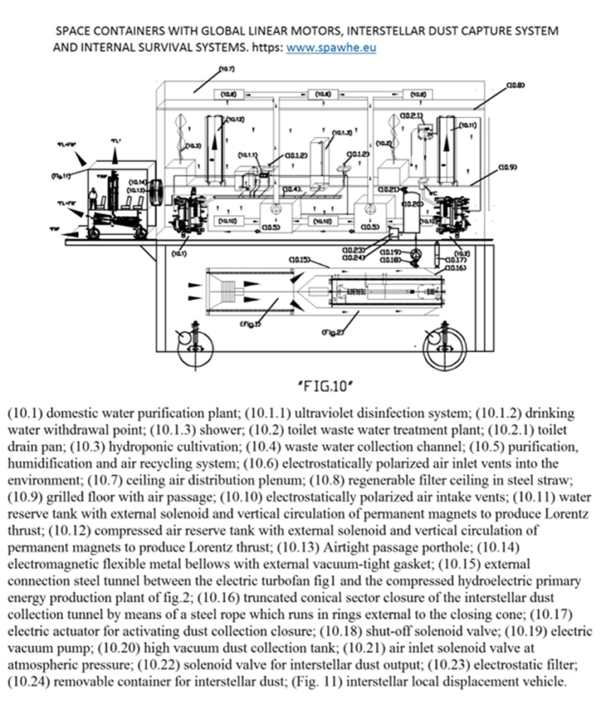
Of the above, the current world ruling class, public and private, has not financed even a comma. On the other hand, they invite me to conferences all over the world, but I should go at my own expense, with the income of my modest pension that does not reach 2,000 euros a month. As said above, after having spent over 20,000 euros to pay the costs of filing patents, which being of public social utility and only intellectual, should not have paid any tax, just as writers who cannot find publishers do not pay any tax. The legislators of the WIPO (World Intellectual Property Organization) who have granted international industrial patents to inventions that are wrong from an environmental and energy point of view, and denied intellectual property to inventions that are correct from both an environmental and energy point of view, will have to repair the mistake made because global inventions that are correct from both an energy and environmental point of view, which do not exist today, have a much higher value than a fantasy novel or a successful song to which intellectual property is recognized. My forty intellectual patents are spread across about 130 articles accessible to all. Some publishers would like to publish them exclusively and even be paid to do so. I reply that I am not an academic, I do not earn titles and I do not obtain academic or corporate career advancements. With the WIPO laws I am not even entitled to intellectual property on my inventions and articles. Several financiers offer me long-term loans at convenient rates, but I am old now. I am not looking for financiers but investors, because as I wrote in this article, sustainability cannot be improvised. It is designed globally. There are still no human-made plants designed globally on planet Earth. They are called thermal, nuclear, solar, wind, biological, chemical, hydroelectric with hydraulic jump, which have the defect of dispersing water and facilitating floods. The energy of the future must be extracted from the earth’s system that wastes nothing and recycles everything. If we ever go seriously into space, we will not be able to do so by continuing to spread dangerous space debris around the Earth because science has not been able to design energy-autonomous plants, capable of combining Newtonian and Lorentzian thrust and therefore capable of returning to Earth for maintenance and overhaul. If we are able to combine Newtonian and Lorentzian thrust, as I have described in my publications, we could also avoid spreading satellite garbage around the planet by planning a return to Earth at a controlled speed without destroying the satellites.
Also doing considerable damage are satellites from SpaceX subsidiary Starlink, which has nearly 7,000 satellites in orbit at the time of writing. As described in a recent Medium article (https://medium.com/age-of-awareness/the-space-junk-problem-is-getting-dramatically-worse-rebecca-jean-t-b5795144afdba), Starlink began launching these satellites in 2019 with the noble goal of providing satellite internet around the world, with a focus on rural areas that lacked access to other types of connectivity. However, a road paved with good intentions still has its unintended consequences. Astronomers aren’t too thrilled about billionaires like Elon Musk dominating the night sky with highly reflective satellite constellations. While it’s worth mentioning how SpaceX is innovating in space sustainability in other ways, this is an area that many astronomers are concerned about for the future of ground-based observations. Space debris has many consequences. Impacts on Earth, collisions with spacecraft, upper air pollution, and light pollution in otherwise dark skies are all negative impacts of the increasing levels of space junk.
The SPAWHE system means Sinergic Plants, Artificial Welling, Hydroelectromagnetic energy: https://www.spawhe.eu. I claim the intellectual property of my inventions and articles that have cost me a lifetime of work unpaid by anyone, in addition to the costs of filing patents that lapsed due to the absence of public and private interlocutors. If I am not mistaken, intellectual property expires seventy years after the death of the authors. SPAWHE S.P.A. could do what governments and multinationals did not want to do, financing all of Spawhe’s inventions and demonstrating that global warming is due to men’s wrong energy and purification inventions. Obviously, SPAWHE S.P.A., represented by the undersigned, after the practical demonstrations of the practical functioning of the plants designed by the undersigned, must be recognized as industrial property or at least intellectual property. I, who have no capital, can only claim my copyright with legal action against WIPO, which is a United Nations body. Only by finding investors, I can prove that global warming can be fought with my inventions. I don’t just need financiers. There is a lot of work to do and I can’t continue to work alone at seventy-six years old.
Luigi Antonio Pezone